I wired up one of these and it seems to work as expected. It uses capacitive feedback to set the gain in a microphone interface. The FET on top is an AC only current source. The beauty of this circuit is that the input is a virtual ground, and several sources of distortion are eliminated. I also expect that back to back diodes could be used instead of the 1G Ohm resistor for bias. I will confirm this when i get some BAV199's (the diodes need to be ultra low leakage). The resistance at the origin for a diode is related to Vt/Is.
Attachments
Hi Scott!
First off, thank you for sharing. It's a very neat design and I'd appreciate it if you could answer a few question for me:
1. Have you measured the pulse response of the mike-amp?
2. The quality of the Cf cap might be critical in this design. Do you have any preferences regarding the cap type?
3. In my experience, FETs may be effectively used as low-leakage diodes. What are you thoughts on this? Have you tried that?
Thanks,
Milan
scott wurcer said:The beauty of this circuit is that the input is a virtual ground, and several sources of distortion are eliminated.
Excellent design!
Yes, I removed the comment that a spare FET makes a good low leakage diode to get the picture to fit into the 1000x1000 pixel limit. I made some measurements on an "air" wired BB that showed beauitful square wave response but was oscillating at 400MHz. The PC board and the 100 Ohm snubber cured that. I hope to characterize this more soon. I did look at using standard BAV99 clamp diodes instead of the 1G resistor and could see the increase in low frequency noise so I assume the theory is right about equivalent diode resistance at 0 V. I need to try known low Is diodes and confirm this.
The capacitor quality must matter but for low values there are lots of options, not the least of which is a sealed vacuum cap.
I still wonder about other applications of this since your feedback impedances have no real part they contribute no noise.
One caveat is that the value of the capacitor that AC couples into the top FET current source is somewhat critical for low frequency flatness. You can get a nice flat response down to 2 or 3 Hz with the right capsule (at least in simulation).
Re: Re: Capacitive feedback, anyone tried this?
Thanks, I started this line of thought when National and others introduced mike interface IC's with MOSFETs and back to back diodes on the input. Open loop the diodes severely limit dynamic range. Mike designers are still skeptical about dumping those huge bias resistors. But without them you can get everything at Digikey and cheaply to boot.
mikeks said:
Excellent design!
Thanks, I started this line of thought when National and others introduced mike interface IC's with MOSFETs and back to back diodes on the input. Open loop the diodes severely limit dynamic range. Mike designers are still skeptical about dumping those huge bias resistors. But without them you can get everything at Digikey and cheaply to boot.
I still wonder about other applications of this since your feedback impedances have no real part they contribute no noise.
Are you thinking capacitive phono cartridge?
SY said:
Are you thinking capacitive phono cartridge?
Not exactly, those MEMS capacitances are just SO small that other things get difficult. We are are working on some exposed die packages so I suppose you could glue a stylus right on a chip, but the electrostatic restoring force for a couple of grams tracking would probably be thousands of volts. There were those electret cartriges, do you know if their internal losses were low enough to benefit? The microphones are actually limited by the internal Q and air damping in the end. You really can't beat thermodynamics and physics.
I wasn't thinking so much of MEMS as I was about something much more conventional, more like the old Weathers cartridges. The Weathers used a conventional suspension and cantilever, but instead of coils and magnets, it had a plate at the end of the cantilever which wiggled around a plate fixed in the cartridge body. The variable capacitance frequency modulated an RF oscillator.
EC8010 said:Tim de Paravacini mentioned this technique being used in Neumann microphones at ETF06. And that was with valves.
Yes, I saw this in the files section over on the micbuilders yahoo group looking for prior use. I was surprised it never made it over to solid state mikes (I couldn't find it). I was also worried that there was something I was missing about running a capsule into a short vs. open circuit and I figure if it worked for them it must be OK.
Actually some of those RF mike techniques are also interesting but not easy DIY.
SY said:I wasn't thinking so much of MEMS as I was about something much more conventional, more like the old Weathers cartridges. The Weathers used a conventional suspension and cantilever, but instead of coils and magnets, it had a plate at the end of the cantilever which wiggled around a plate fixed in the cartridge body. The variable capacitance frequency modulated an RF oscillator.
I see, similar to Baxandal's 1963 RF microphone technique. Weathers predates that several years. I guess one needs to do an analysis from basics on the ultimate dynamic range and SNR of each technique. Though the RF mikes have an advantage in high humidity which is another issue.
"...and it is not recommended for any household in which more than one person has access to the phonograph. For bachelors, or people with unnaturally good control over the spouse and children, the Weathers is excellent. For others, it is just too delicate."
SY said:Well, geez, that true of any phono system worth having. I've got mine behind a cage.
That creates some amusing mental images. BTW, when will you let the phono stage out of the cage?
Sheldon

Sheldon said:
BTW, when will you let the phono stage out of the cage?
Sheldon
When my child reaches 18 and all my cats have died of old age.
@EC8010 and darkfenriz
The charge amp technology was used by Neumann in their famous KM83/84/85 (picture below) and 47fet mikes. As far as I know, the topolgy was used to linearize the transfer function of the active element (fet), which is inferior to the tube transfer function characteristic. More info can be found on the Neumann website in "Basics of Microphone Technology" (.pdf).
Phantom power is mandatory for the supply of active circuitry in a condenser mike. One other thing: if we were to use the true condenser capsule, we would need to polarize it. Scott, on the other hand, obviously used the pre-polarized capsule (electret) in his example.
Regards,
Milan
Attachments
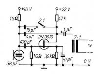
Neat, thanks for finding that. I was also trying to not use any electrolytic capacitors in the signal path. The 2N3819 in that circuit has sort of a modest gain so I would think the distortion would be a little worse. That active FET load gives an almost 40dB open loop gain.
In the end this is the same general principle and I wonder why it has not worked its way into the general bag of tricks for DIY micbuilders.
It's true the issues of general practice for phantom power, etc. were not addressed. I was going to just use single ended out and the third wire as +9V supplied by the preamp. For short mike runs this is probably no problem.
As this idea seems to originate from the usage of the Nakamichi CM-300 microphone (manufactored by Primo, still!). That microphone is powered by an internal 9V batteri (dia 19 and length 51 mm). That batteri is now hard to find but there are many substistutes. Some manufactors (like Didrik de Geer) of the highest quality microphones avoid phantompower for some reasons.
- Status
- This old topic is closed. If you want to reopen this topic, contact a moderator using the "Report Post" button.
- Home
- Amplifiers
- Solid State
- Capacitive feedback, anyone tried this?