I am working on a preamp and have been thinking about the supply topology after reading some of the threads on the forum.
Here is what I've basically come across
1. Straight series pass linear voltage regulator - LM317 thru to low noise discrete variants (examples from Borberly, Walt Jung et al)
2. Voltage + Shunt variants (Curl - I think if I read comments correctly
3. Constant Current/Shunt distributed toplogy
4. . . ?
For # 3, I envisage a constant current source (one for + and 1 for -) that feeds the 3 or 4 preamp stages through a resistor of between 150 - 200 Ohms at each stage. At each amplifier stage, a localised shunt regulator maintains a constant voltage.
The advantages as I see them are:-
a. All the supply lines are constant current - there are no radiated magnetic fields
b. The return lines to the power supply are also constant current except for the load current returns, which would be run separately back to the central return ('mecca')
c. Only place where magnetic fields (=cross coupling) are generated is right in the vicinity of the shunt regulator. with careful layout, the loop area can be kept very small.
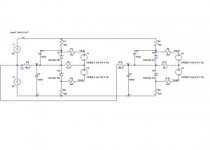
I've done a bit of simulation work - see attached LT Spice diagram to confirm the topology benefits. for the shunt regulators, I am thinking about straight Zeners in parallell with 100uF and 1uF WIMA. This weekend I am going to do some practical tests using the zener/cap combo vs an LM317 and a NE5534 and some headphones.
Any other schemes/feedback?

Here is what I've basically come across
1. Straight series pass linear voltage regulator - LM317 thru to low noise discrete variants (examples from Borberly, Walt Jung et al)
2. Voltage + Shunt variants (Curl - I think if I read comments correctly
3. Constant Current/Shunt distributed toplogy
4. . . ?
For # 3, I envisage a constant current source (one for + and 1 for -) that feeds the 3 or 4 preamp stages through a resistor of between 150 - 200 Ohms at each stage. At each amplifier stage, a localised shunt regulator maintains a constant voltage.
The advantages as I see them are:-
a. All the supply lines are constant current - there are no radiated magnetic fields
b. The return lines to the power supply are also constant current except for the load current returns, which would be run separately back to the central return ('mecca')
c. Only place where magnetic fields (=cross coupling) are generated is right in the vicinity of the shunt regulator. with careful layout, the loop area can be kept very small.
I've done a bit of simulation work - see attached LT Spice diagram to confirm the topology benefits. for the shunt regulators, I am thinking about straight Zeners in parallell with 100uF and 1uF WIMA. This weekend I am going to do some practical tests using the zener/cap combo vs an LM317 and a NE5534 and some headphones.
Any other schemes/feedback?
Attachments

Hi,
the three resistors after the regulators completely ruin the regulation into each stage.
The statement
As soon as a signal is passed the lines carry variable current. Is the pre-amp single ended or push pull? Is it fully complementary and/or balanced?
the three resistors after the regulators completely ruin the regulation into each stage.
The statement
only applies during quiescent conditions.All the supply lines are constant current - there are no radiated magnetic fields
As soon as a signal is passed the lines carry variable current. Is the pre-amp single ended or push pull? Is it fully complementary and/or balanced?
Andrew,
the low value resistors in the ground lines simulate the track resistances.
The resistors connected to the voltage sources at each shunt regulators simulate the load current drawn by the various op-amp stages.
The resistors in series with the shunt regulators isolate the shunt regulators from the current sources.
Without these, the lowest voltage shunt regulator would carry all the non-load current - so we would end up with the same situation as would be the case with a normal voltage regulator - varying current in the supply lines - i.e. noise.
Since all the stages are fed from a current source, the current in the lines to each the shunt regulator (zeners in this model) is constant - the only place it varies is between the load and the local shunt regulator. Because these are in very close prximity, the loop area can be kept small, so radiotion, and this coupling to other stages minimized.
are you sure?Bonsai said:Just to re-iterate, the current in the supply lines is constant - the only place you see change is between the shunt regulator and the load. The current in the ground returns line is also constant.
The current supplying a ClassA stage varies with the output current.
Bonsai said:Just to re-iterate, the current in the supply lines is constant - the only place you see change is between the shunt regulator and the load. The current in the ground returns line is also constant.
I don't understand where is the concrete advantage of displacing variable current (and somewhat variable magnetic fields) from a point to another of the same circuit.
Further, if a magnetic field shielding is needed is better worth pairing the going/return path of the currents with bifilar connection as ever used from the early time of electronics... and left the current itself behave freely as required by circuits and loads...
Bho!
Piercarlo
Piercarlo,
one of the problems I see with conventional supply topologies (voltage regulator feeding multiple stages) is that layout is quite critical. The + and - rails carry a dynamic current load, and the ground current also varies. All these factors contribute to the noise floor. In most cases it is not possible to design a layout with a voltage regulator topology feeding multiple stages that completely eliminates these noise problems. The idea behind the proposed topology is that the supply and ground lines feeding the various stages carry only a DC curent (in practice I expect there is some dynamic current variation, but it is in the order of 10-20 times lower than a purely voltage based topology). The benefit of this approach is that it facilitates a much lower overall noise floor. If you now add the screening etc that you talk about, imagine the kind of performance that could be acheived.
one of the problems I see with conventional supply topologies (voltage regulator feeding multiple stages) is that layout is quite critical. The + and - rails carry a dynamic current load, and the ground current also varies. All these factors contribute to the noise floor. In most cases it is not possible to design a layout with a voltage regulator topology feeding multiple stages that completely eliminates these noise problems. The idea behind the proposed topology is that the supply and ground lines feeding the various stages carry only a DC curent (in practice I expect there is some dynamic current variation, but it is in the order of 10-20 times lower than a purely voltage based topology). The benefit of this approach is that it facilitates a much lower overall noise floor. If you now add the screening etc that you talk about, imagine the kind of performance that could be acheived.
Bonsai said:Piercarlo,
one of the problems I see with conventional supply topologies (voltage regulator feeding multiple stages) is that layout is quite critical. The + and - rails carry a dynamic current load, and the ground current also varies. All these factors contribute to the noise floor. In most cases it is not possible to design a layout with a voltage regulator topology feeding multiple stages that completely eliminates these noise problems. The idea behind the proposed topology is that the supply and ground lines feeding the various stages carry only a DC curent (in practice I expect there is some dynamic current variation, but it is in the order of 10-20 times lower than a purely voltage based topology). The benefit of this approach is that it facilitates a much lower overall noise floor. If you now add the screening etc that you talk about, imagine the kind of performance that could be acheived.
Well, IMHO layout of distributing currents and supplies to different circuits is a minor question. The real question is, simply, that a single PSU for many circuits can't grant nothing but the stableness of DC voltage delivered. Other problems, included those related to noises of various kind, simply CAN'T be defeated only managing to have a a cleaner or "quiet" PSU; even if you get the best cleanest PSU allowed by the technology!
Noise (and distortion also) questions must be counteracted only with local measures (screening, especially *articulate and separate screening on a stage by stage bases as usually done in RF circuits*, is the top of concern; many interfering and noisy phenomena are of totally *external* origin and there are no mean of defeat them only with circuital tricks (as lowering the working impedance of the circuit and similars or, on PSU side, beefing up filter capacitors or active ripple filter); these means can just attenuate the problems, not solve it.
Instead of make constant the currents draw by circuit is more fruitful reduce all the phisical parasitic elements which may be triggered to disturb by any varying voltage or current variations (which CAN'T be avoided if you want a circuit able to do some useful work more sophisticated than of lighting an incandescent bulb or a boiler. Even a galvanic bath is not a constant current load).
A better study of layout (with it's physical tridimensional issues about the influence and autoinfluence of real circuits that, is worth remembering in an era of extensive and raw simulation of anything appear to be "electronic", is incoercibly different from any "model" or "paper circuit" what has became customary to linge for many enthusiast. 2D world is more simpler than 3D world... Sometime TOO simpler...) may conduct to a better, stable and consistent result than any circuital "trickying" which, at most, can assiste the layout in defeating or accomodating the problems ineluctably put in field by the Physics (and noise is mainly a physical, not a circuital problem).
Ciao
Piercarlo
IMO an active device is better to react not only to the noise in the PS, but also react to the varying current demand to maintain a steady rail voltage and this varying current may contain higher freq harmonics that could show up as voltage change if active circuit(s) are not fast enough to compensate. Higher bandwidth regulater(amplifier) can make a large difference. After all aren't we listening to the power supply simply modulated by the audio signal?

The concept is that the loop areas where there are dynamic current variations is kept as small as possible, and these are more easily isolated from stage to stage usung this topology. This is more difficult with a straight voltage source topology when you have to run long PC traces and can lead to coupling of noise (inductive, capacitive, loop resistance) into the different stages via the supply lines and the ground lines (IxR noise).
If you are feeding a constat DC current to the stages, the effect of these mechanisms can be reduced. for the concept to be effective, you have to keep the loop area around the active circuit stages and the shunt regulators as small (tight) as possible.
Again, if you run the simulation (and I accept it uses ideal components and reality may be a little different) you can see that the current into the branches (= small signal amplifier stages in a preamp - like an IC or discrete op-amp) is constant and the ground return current is also constant. Replace the main current sources with voltage sources and repeat the simulation - the current in the main feed varies, as does the ground return current.
I envisage this in a situation where there is probably a volume control, amplifier stage and then a buffer stage. Prior to the volume control, probably two active balanced inputs and a tape loop buffer. The active stages all draw about 10 -10mA each, except the output buffer which may be called upon to deliver 20-30mA into low loads.
Regards
everyone can see that your philosophy depends entirely on constant current supply and constant current amplifier + constant current buffer. What if the amp and/or buffer is not constant current?Bonsai said:.............If you are feeding a constant DC current to the stages, ............... you can see that the current into the branches ....... is constant and the ground return current is also constant. ...................I envisage this in a situation where there is probably a volume control, amplifier stage and then a buffer stage. Prior to the volume control, probably two active balanced inputs .......
This statement
implies you plan to use conventional amplifying stages. These are not constant current. A discrete ClassA stage does not draw constant current from the supply rails when delivering AC current to the load.current into the branches (= small signal amplifier stages in a preamp - like an IC or discrete op-amp) is constant
What are you using to amplify the signals in the pre-amp?
Please post a schematic.
AndrewT said:This statement implies you plan to use conventional amplifying stages. These are not constant current. A discrete ClassA stage does not draw constant current from the supply rails when delivering AC current to the load.
What are you using to amplify the signals in the pre-amp?
Please post a schematic. [/B]
As addendum. If there is not constant current circuits, then you can obtain the same result of a costant current flowing (absence of varying magnetic field, which appear to be your main goal) paying adequate care, in designing layout, to its *simmetry*. If you design tracks carrying the same kind of current (input, output, supplies...) in a way which opposite fields couples and null by itself, you earn the same result of suppliyng your circuit with constant current but *without any concern about constant current* that may be uselessly hard to defeat. Imho at least.
Hi
Piercarlo
Andrew, the amplifier stages do NOT have to be constant current. At the localized amplifier stage there are two paths the constant current supply can take: Through the amplifer and load and through the shunt regulator. When the amplifier+load current goes up (because the gain stage is driving a load), then the current through the localized shunt regulator goes down. Likewise, when there is no load current flowing, or the load current reduces because the signal reduces, more of the current flows through the shunt. In this way, the total current into the amplifier stage remains constant with the benefits described earlier.
Of course, the current shunts are not perfect (e.g impedance rises with frequency) , but then neither are voltage regulators. However, I think that this topology, when applied to small signal amplifier stages, can provide an important overall reduction in the system noise floor before other more conventional methods are applied like careful layout, screening, shielding, ground returns etc
Of course, the current shunts are not perfect (e.g impedance rises with frequency) , but then neither are voltage regulators. However, I think that this topology, when applied to small signal amplifier stages, can provide an important overall reduction in the system noise floor before other more conventional methods are applied like careful layout, screening, shielding, ground returns etc
Re the question about the amplifier stage schematic - you can use an IC opamp of your choice. All that you need to make sure of is that the constant current supply is > than the worst case op-amp quiescent current + load current. Any unused current will be shunted around the op-amp and load bu the total current into the stage will remain constant. You of course can use a discrete amplifier as well - e.g Lineup's design posted recently.
- Status
- This old topic is closed. If you want to reopen this topic, contact a moderator using the "Report Post" button.
- Home
- Amplifiers
- Solid State
- Supply Topology/Grounding for Pre-amp