wojtek5001 said:What is R1 and R11. They will dissipate lot power. Isn't better to simply connect emiters by resistor, like in many others amp?
It is a very simple way to discharge the base junction at HF and to prevent negative base impedance
Hi,
the Cordell thread seems to have confirmed that BJT output stages need about 15mV to 25mV across each of the emitter resistors to stay at or near optimum bias to help hide crossover distortion.
They also agree it is better to err on the high side rather than the low side (variations with junction/ambient temperatures) to stay above the 15mV lower limit for all operating conditions.
Your 100mA and 0r1 put you too far below the 15mV.
If you follow their advice then either bigger Re or some big sinks to dissipate more Iq.
Parallel pairs with low value Re will require more precise matching than with higher Re values.
I don't follow the diamond arrangemment of the emitter resistors on the drivers. I have to leave that to the experts.
wojtek5001 said:What is R1 and R11. They will dissipate lot power.
Isn't better to simply connect emiters by resistor, like in many others amp?
I have to agree.
So if this is good,
why don't you replace R5 with 2 resistors to supply lines?
Now, if it is good in place,
it is most probably good in the other place.
So:
Replace R1 / R11 with one resistor between emitters.
Just like R5.
The current variations caused by R1 and R11 which are loading the drivers
can NOT be good.
Imagine +/-20 Volt across those resistors ......
Besides, I think PSRR (supply rejection ratio) will be worse with those resistors.
Questions:
- What Supply voltage, you had in mind?
- What Output power you had in mind,
- And into What Load?
Regards
lineup
Hi
What kind of front end is biasing this circuit?
It seems to me that R1 & R11 would cause Q1 & Q3 to conduct asymetrical current(referenced to audio voltage) and the input stage would have to correct for this extra error. If these resistors were replaced with CCS's, the impeadance above the CCS bias setpoint is very high and would reduce this extra error current load. I agree with wojtek5001 about the resistor/cap. Why wouldn't this work at higher frequencies? The point of this cap is to prevent cross-conduction at high frequencies by discharging the bases to turn them off. R5 could have a parralel cap as well. Base resistors will not cause as much phase shift as the extra darlington transistor will, as opposed to a two stage darlington. Maybe reduce the gain slightly but insure more equal current sharing. Vbe multiplier may be helpful in controling output bias setpoint.
Yes Lineup, PSRR would be worsened....
Hi, Roender,
R1 and R11 are interesting. Electrocompaniet 25WclassA also uses these resistors. In the later Electrocompaniet amp, R1 and R11 are replaced by CCS.
How do you know it can prevent "negative base impedance"?
R1 and R11 are interesting. Electrocompaniet 25WclassA also uses these resistors. In the later Electrocompaniet amp, R1 and R11 are replaced by CCS.
It is a very simple way to discharge the base junction at HF and to prevent negative base impedance
How do you know it can prevent "negative base impedance"?
R1 and R11 is a well known practice in HF amplifiers, where is a must to use BE resistors.
CCS instead those resistors is a very good idea (will improve PSRR also).
The base current in predrivers is to small to replace r5 with cross resistors like in final stage.
The target power is 100w in 8ohm, power BJT's will be NJL0302/0281
CCS instead those resistors is a very good idea (will improve PSRR also).
The base current in predrivers is to small to replace r5 with cross resistors like in final stage.
The target power is 100w in 8ohm, power BJT's will be NJL0302/0281
lumanauw said:
How do you know it can prevent "negative base impedance"?
Hi lumanauw,
From the realm of ignorance, what do you mean by "negative base impedance"?
 Probably something familiar, but I haven't heard that term before.
Hi, CBS240,
Triple darlington can oscilate (not only CFP). The cause is the base impedance can turn into "negative". This happens because actually base impedance has imaginary number (i+jw).
The way to deal with this is to put base stopper resistor.
http://www.diyaudio.com/forums/showthread.php?s=&threadid=70309&highlight=
I don't know if putting R1 and R11 (to rails) can also fix this negative base impedance effect.
roender said:R1 and R11 is a well known practice in HF amplifiers,
where is a must to use BE resistors.
CCS instead those resistors is a very good idea (will improve PSRR also).
The base current in predrivers is to small to replace r5 with cross resistors like in final stage.
The target power is 100w in 8ohm, power BJT's will be NJL0302/0281
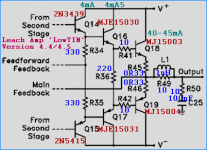
HF amplifiers. But this is a LF amplifier.
CCS is better, but makes circuit more complicated.
Commonly seen practice in audio amplfiers:
1. Put resistor between emitters of drivers.
2. Put one resistor from Upper driver Emitter to Output node.
And a corresponding resistor from Lower emitter to output.
I think this second option is well worth a try.
Neither of us are professors.
But maybe we can teach professors things ...
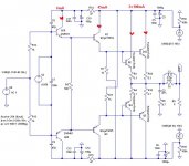
Professor Leach, in his LowTim amplifier uses only one resistor between emitters.
As can be seen in his output stage here.
Actually he has written one whole separate page about his output stage:
Leach - The Output Stage
In my attachment below here
I have added the values of those components, in Leach Amplifier.
Regards, lineup
Attachments
For a similar idea, see:
http://home.no.net/andiha/articles/audio/clclssfig/clclasch.gif
He calls this a Class A amplifier, but to me, it looks like it's really heavily biased Class AB.
The E202 devices are 2mA current diodes. I guess you could use a similar arrangement with a FET.
http://home.no.net/andiha/articles/audio/clclssfig/clclasch.gif
He calls this a Class A amplifier, but to me, it looks like it's really heavily biased Class AB.
The E202 devices are 2mA current diodes. I guess you could use a similar arrangement with a FET.
- Status
- This old topic is closed. If you want to reopen this topic, contact a moderator using the "Report Post" button.
- Home
- Amplifiers
- Solid State
- Triple EF BJT power stage.