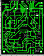
Hello Geoff
I did a careful check on the layout and it seems to be ok, as far as I
can tell. Doing my boards by hand I aquired a little experience in checking the boards I make (terrible pain), so I did it with the utmost
confidence.
If by any chance you decided to make a high resolution copy of the
copper patern, I think it will be ok.
Thanks
Hi,
this layout will be different and may require different compensation.
Zobel across the speaker terminals. A better place for it.
The phase change introduced by the DC block on the input sets in much earlier than the DC block on the NFB path.
The existing 165mS filter on the input and the 470mS filter on the NFB are already a factor of 2.8 apart (1.5octaves).
There is some merit in having a large and good quality cap on the NFB leg and D.Self says the AC voltage across this cap should be checked to be less than significant on low frequency signals.
Does anyone have experience of measuring this AC voltage?
BTW.
a 6V3 cap on the NFB leg is OK when the amp is working correctly, but this cap may break down if the output offset becomes high and then troubleshooting becomes more difficult. How about adding a pair of series Zeners or inverse parallel diodes to save the cap and the input stage?
jmateus said:
Hello Geoff
I did a careful check on the layout and it seems to be ok, as far as I
can tell. Doing my boards by hand I aquired a little experience in checking the boards I make (terrible pain), so I did it with the utmost
confidence.
If by any chance you decided to make a high resolution copy of the
copper patern, I think it will be ok.
Thanks
The hi-res image only takes a minute or two to produce but now that the layout has had an independant check I will make some (most?) of the traces wider before generating it. After all, there is no point in etching away more copper than is necessary. If any further comments or suggested modifications come in then it is an easy matter to amend the layout and produce another copper pattern.
Hi,
I just ran some numbers on 1pair of MJL4281/302 @ a sink temperature of 40degC (Tc<=50degC) and supply rails @ +-38Vdc and the result was a pleasant surprise.
50W into 8ohm at 60degree phase angle and one second SOAR.
but also safe into 4ohm at the same 60degree phase angle of a reactive load.
The downside was the poor power delivered into low impedances.
76W 4ohm, 82W 3r, 86W 2r.
Seems like a good 8ohm amplifer that could also drive 4 to 8ohm reasonably well. Something the original would struggle to stay reliable with.
Geoff said:Attached is the modified board with wider tracks where feasible.
Geoff said:Attached is an image of the copper pattern as viewed from above (the component side of) the board.
You are so kind, Geoff
Good work.
I wouldn't be surprised to see several other, join in with jmateus
and build this Cyrus One amp.
Using this PCB layout.
Not destroyer X, though.
He is so busy with building 10 other projects.
Will be years before he will have time for a Cyrus
lineup
lineup said:I wouldn't be surprised to see several other, join in with jmateus
and build this Cyrus One amp.
Using this PCB layout.
It might be better if just one person built it first to make sure that it works!
Geoff said:
It might be better if just one person built it first
to make sure that it works!
Yeah.
As a ginneapig.
( how do you spell that word: gunnieapig )
by the way,
I have heard some Kings & Emperors in history
had someone employed to taste their food.
If this one survived - Emperor would eat .....
Hi Spind,
one runs the combined decoupling and Zobel return to the Central Audio Ground.
A separate wire is also run from the signal ground to CAG. This signal ground wire can be from either the PCB or from the isolated RCA input socket, whichever is quieter.
That reminds me.
Geoff,
consider adding an on board resistor connection between signal ground and decoupling ground. It provides a lower inductance path between the two sides of the PCB.
spind said:I may be missing something, but does the signal ground connect the main ground on the board or do you just run a wire from the input ground terminal to a star ground off the board?
Andrew has covered the two ground returns, power ('dirty') and signal ('clean'), in his reply but it may help to look at the power supply schematic for the Cyrus1:
http://www.tcaas.btinternet.co.uk/cyrus1ps.gif
Here you will see the three different ground symbols and how they relate to each other. Also note the presence of R121, a 15R ground lift resistor. There is no protection for this resistor so if a fault causes a significant current to flow to the mains ground this resistor is likely to blow. Not a particularly good situation!
lineup said:( how do you spell that word: gunnieapig )
Guinea-pig
AndrewT said:Geoff,
consider adding an on board resistor connection between signal ground and decoupling ground. It provides a lower inductance path between the two sides of the PCB.
Andrew
I agree with many (most) of your commments, for example providing protection for the feedback capacitor etc, and these are things that I may well have included had I been producing a design from scratch or modifying (improving) an existing circuit. However, the object of this exercise was to replicate the original Cyrus 1 circuit as that was in what jmateus expressed an interest.
Now if he were to ask for an 'improved' Cyrus 1 then it would be a different matter.
Geoff
Hi Geoff
That was so kind of you, I thank you very much.
The board looks exactly what I had in mind, small and pratical to
assemble.
Definitely I'll be building the Cyrus as soon as I buy some board
material, I'm out of it and I didn't realize it. But that will be a matter of a few days, as soon as I get the board I'll be starting the project and
I let you know guys the progress.
Carlos, no, as was said he's busy with his studies about the ULTIMATE
amplifier so I won't disturb him in his profound cogitations. But
there is always a hope, if the Cyrus turns out to be a winner (as I
think) I'll tell him and may be he'll convince himself that those profound
thoughts are not worth and may be, just may be he'll go for it.
Thanks again Geoff, you made my week.
Nice Work!! Would anyone consider making some boards to sell to us DIY'ers?
The heatsinking looks alot smaller than the original Cyrus. I know that the same heatsink was used for the more powerful Cyrus Two though.
Looks like a neat little amp and the idea of monobloc construction interests me when compared to the original.
Active speakers anyone?
I can't wait to see how this one turns out.
cheers,
Martin.
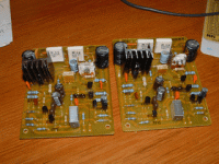
The right side driver doesn't have the final heatsink, it interferes with
the adjusting pot shaft so it will be installed after the adjustment.
That's exactly the planned final amplifiers, two monoblocks. I hope
everything comes out ok, let you guys know the progress.
Wish me luck
the adjusting pot shaft so it will be installed after the adjustment.
That's exactly the planned final amplifiers, two monoblocks. I hope
everything comes out ok, let you guys know the progress.
Wish me luck
jmateus said:The right side driver doesn't have the final heatsink, it interferes with
the adjusting pot shaft so it will be installed after the adjustment.
The original Cyrus doesn't have heatsinks on the two TO-126 driver transistors which is why I didn't allow any space on the pcb for them.
Post Script: I was also anticipating top-adjust presets.
- Status
- This old topic is closed. If you want to reopen this topic, contact a moderator using the "Report Post" button.
- Home
- Amplifiers
- Solid State
- Cyrus 1 project

