Keep the filter network for your gainclones...
It is mostly beneficial to the inverted configuration though, and for NI GCs you can try without some... when I still used an active buffer (I have an integrated design now, which doesn't need it) I removed the last cap there at the output for my My_ref_C, and it certainly made the sound even more revealing.
For a properly designed and assembled NI GC the best buffer may still be no buffer...
The other filter bandlimits the amp to keep HF garbage out...
lineup said:")
Pedja Rogic JFET Buffer is a good circuit.
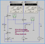
Here is my own approach for a DC-in and DC-out Buffer.
I use a one JFET + one BJT Follower.
At 5 mA, BC550C has VBE like +0.660V.
At like 1.65mA, JFET BF245A has VGS like -0.660V.
Add those, and I get 0.000 Volt offset at the output.
The BC550C does what it is best for: Provide current.
The JFET BF245A does what it is good at: Provide High Input impedance.
Circuit can be made very fast. 1 MHz is no problem!
Also shows very nice low distortion, without any feedback.
Most of the low level distortion is in fact 2nd harmonics.
Enjoy
lineup
Lineup Audio Lab
Yo Lineup, your circuit looks interesting. Can it also function as a good linestage (without gain) by replacing the 100k with a 100k pot? The 5mA CCS can be replaced by a 4.7mA current regulating diode? Will it drive other like tube power amps well too?
cheers!
Hi Nordic,
I'm glad this thread has been revived! I had never seen it and a clear layout design for perfboard is exactly what I had been looking for.
I have been considering adding a buffer to my LM3886 chipamp (the Carlosfm design) and thought about adding Pedja Rogic's or the new Pass B1. Since the Pedja's one has been tried and tested for a long time I think I will go for it.
I just have some questions.
1- Do I need to change any values for my particular chipamp?
2- Can I run the buffer it with a basic regulated ready made wallwart type PSU?
3- Do you have any suggestion in terms of type and quality of specific components?
Many thanks for your help.
Regards
Antonio
Sanchez, I would build it with what you have at hand... there is more to be had from topology than parts...
These work great with chipamps, as it forces the amp to work in a limited frequency band, more suited to its abilities.
Mine was not very full of nonsense with the PSU, but if you hear a buzz, appart form ground noise I would look for a small transformer to make a PSU, I used a 15VA 15V transformer, and this is likely overkill.
pengboon said:
Yo Lineup,
your circuit looks interesting.
Can it also function as a good linestage (without gain)
by replacing the 100k with a 100k pot?
The 5mA CCS can be replaced by a 4.7mA current regulating diode? Will it drive other like tube power amps well too?
cheers!
first look at my attached shematic
A)
We have two BF245A as input stage
It is important that is BF245A (not B/C)
As at ~ -0.650 Volt GateSource,
the BF245A should have something like 1.65 mA current.
(I am sure we can use BF245B but not at this current level.
And like 1.5-2.0 mA is well enough to drive one BC550C, hfe-gain >400 )
B)
One BC550C as output stage = Follower.
Volt B-E is something like 0.650 V .. at normal currents.
BC550C works best at 1.0 - 5.0 mA.
I have used 5 mA, as this gives maximal output current
and so can drive any load rather well.
Of course this output stage can have most any other LowNoise TO-92.
As being in Europe, we can buy BC550C and get them for almost nothing
But 2N5550, or 2N5551 and 2SC2240 or whatever would work as well.
Even BD139 ... one TO-126 should be okay. For higher currents.
These all have like 0.6 - 0.7 Vbe, like BC550C.
The current can be anything in output.
As long as not more than input BF245A can drive. And this would be quite a lot of current!
BD139 for example could be set to work at 50 mA. No problems, I think.
C)
After setting up the output stage,
the lower BF245A is adjusted with potentiometer or by changing the resistor value of P1.
Pick the resistance that makes 0.00 Volt at output,
when you have connected the GATE of input BF245A to GND (0 Volt)
D)
The Input resistor can be one potentiometer. And just about any resistor.
No problems.
Value will not effect the DC-offset voltage (0.00V) at the output.
You should get always the same DC at output, as you have at input GATE,
if you have setup the P1 correctly.
JFETs work well even with very high input resistors.
So we can use an input resistor / potentiometer with high value.
1 MOhm, 470 kOhm, 100 kOhm 50 kOhm, 25 kOhm .. no problems.
I would not go as low as 10 kOhm.
JFET input does not work as best, at very low input impedance.
To use any prectically any current source for the '5 mA' output is possible.
JFET, like in Input .. CCS Diode .. LED + transistor ..
and even only one resistor to bias Output BC550C will work.
The power supply is not very critical in my setup.
This buffer has got very high PSRR (power supply rejection ration).
So will work well with most.
Of course one regulated dual LM317 + LM337 is always a good choice for preamplifier circuits (and Op-Amp circuits).
See this link I got from pengboon in his email.
goes to Nuuk Gainclone pages:
http://myweb.tiscali.co.uk/nuukspot/decdun/gainclonepre.html
however, remweber that BF245 can have max 30 Volt Drain-source voltage.
So make Nuuk's supply here be: +15V .. 0 .. -15V .. or lower.
An externally hosted image should be here but it was not working when we last tested it.
Attachments
distortion by LPF
Hi,
I'm building the Pedja's buffer and all works well until I added a low pass filter after the 4.7uF DC blocking caps as per Pedja design...(R1=75ohm in series and C1=47nF from the output point to the ground).
The signal gets distorted above 8kHz, the lower part of the signal becoming more like sawtooth...
Both of my circuit are showing the same symptom. Check many times the connection and they look Ok.
Has anybody had an experience with this?
Thanks,
Joshua
Pedja Rogic's buffer + Class A headphone Amplifier
HI,
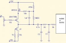
i plan to builds a class A mosfet headphone amplifier - http://diyaudioprojects.com/Solid/IRF610-Class-A-Headphone-Amp/
and wants to add pedja rogic buffer at the input stage.
is any modification required in buffer circuit or amplifier circuit OR can i simply connect them.
Please guide. here is the circuit for amplifier
HI,
i plan to builds a class A mosfet headphone amplifier - http://diyaudioprojects.com/Solid/IRF610-Class-A-Headphone-Amp/
and wants to add pedja rogic buffer at the input stage.
is any modification required in buffer circuit or amplifier circuit OR can i simply connect them.
Please guide. here is the circuit for amplifier
Attachments
AndrewT said:Hi,
the main purpose of a buffer is to allow the unsuitable source to drive the complex impedances of the interconnections and the input of the next stage.
Yes, buffer the volume control. But, you do not need to buffer the input of the headphone amplifier.
hello sir,
i had read lot of praise about this buffer and how it highlights fine details of audio signal, and that's why i want to add before headphone amplifier.
i think i'll experiment running the headphones with and without the buffer.
Hi All
Well I have just come across this thread interesting info here
AS a beginner at this I have some questions to ask if I may thanks for the help chaps
1. Right what I want to do is use the Pedja Buffer in my Dac driven of the vout output s directly of the dac
2. Can I use a 2SK170/ J103 in place of the J310 I have the 2SK170 GL but can’t get the J310s in the UK? But have the J103
Or could I to replace both the 2SK170/J310 with a pair of BF245B without any changes to the schematic of the pedja buffer
A Question for lineup I would like to have a go at your DC on DC out Buffer could I use the BF245B instead of the suffix A version and what value input resistor to use with 2.5volts in from the dac also what value for the output resistor
Thanks all
Did you read the whole thread? Post 38 gives the options for a J310/U310 and there will sources for J310 in the UK - just not at your local hobby shop. Try this obvious source JFET | CPC | Results
Note that circuit operation is dependent on individual FET performance and resistors may have to be tweaked to get it properly operational anyway. BTW, most of this thread is more than 4 years ago, some of the guys don't post any more.
J103? do you mean 2SJ103, J113, J130 or something else, since J103 isn't a FET.
If I use the 2SK 170 GL which I have I then need something to use with the 2sk170 and the one we want is not available in UK and I don’t want to search all over the planet for parts
the only other device I have has J103 GL stamped on them but the invoice clams 2Sj103GL so I need a device to use with the 2SK170GL but the problem is most Devices with 2SC 2SK 2SA and 2SJ are difficult to get here in the uk
I need to find something to work with the 2SK170 or replace both with something new and available in the uk cost and the shipping is to high now for small order cost me more than the buffer just to get a pair CPC N/A stock
I see, sorry about the outdated CPC link. Like Farnell, they seem to have used Fairchild supplies who recently dropped most JFET manufacture. On-semi claim J310 are in full production, however, and I bought some here only last month. There are other distributors too, such as Futurlec. Google is quite helpful tracking down these parts.
The reason for staying with what others have used is because this a unique very high Idss JFET without direct equivalents, but as jacco stated, it's not critical for the role and 2sk170 can substitute but it has lower Idss and you will have to try adjusting the resistors as per his post 38 and Nordics preceding one.
JFETS have broad parameters anyway, which means you will always have to mess with currents manually in each iteration to get them to function within close limits as here.
- Status
- This old topic is closed. If you want to reopen this topic, contact a moderator using the "Report Post" button.
- Home
- Amplifiers
- Solid State
- Pedja Rogic's J-fet buffer for dummies.