Hi guys!
Here we go!
Since i've seen all this project built on this forum (krell 50, krell 100...and so on...), i would like to start a new one.
hope it will catch up your attention...
I would love, if possible with your help of course, to re-design and up-to-date this project.
For example, i think the bumb control circuit for the loudspeaker (which on this project is made with a relè) and the protections circuit could be made better than this.
There are on the ouput stage, two feedback networks:
one network with a cap and res, and a second with an operational amp.
Is it possible to improve and this last one?
Is it possible to lessen the feedback network without compromising the stability?
I don't know if anybody kows gryphon, but they have designed a Microprocessor-controlled non-invasive "smart" protection system
This is just an idea, to design together a system controlled by a micro that would regulate, in a not invasive way, the soft start and the protection system..
Anyways i really hope to see the post of this project growing up!!!
Best,
Stefano.

the op amp is the DC servo, and returns to the noninverting side of the diff amp, not a problem, since it is outside both the signal path and the negative feedback path. negative feedback is fed back to the input of the amp, which is also the inverting input of the diff amp. there is no compensation in this amp, but the inputs have feedback integrating caps, so there's room for improvement there..... remove the caps across the feedback resistors, and add b-c compensation on the driver transistors if needed.
as far as the protection circuit goes, it already looks "noninvasive", since the detection circuit monitors the output collector current, does not interrupt the drive signal, but trips the relay. it's a simple SOA detector.
as far as the protection circuit goes, it already looks "noninvasive", since the detection circuit monitors the output collector current, does not interrupt the drive signal, but trips the relay. it's a simple SOA detector.
About the dc servo:
are there any other way of controlling the dc condition rather than this one?
Basecally that net on the schematic , is a network that by mean a low pass filter takes the output signal and compare it with the ground on the other input of the op amp. Even if the low filter is made with a very low cut off frequency that ideally would control just the dc component of the output signal, as far as i can understand, in the reality it cold interact with the signal and might be a little form of feedback and distortion.
Moreover, about the the bump control circuit, as far as i know, the relè was the first introduced way to keep this issue under control and i think that other design on reguard of this were made during this time.
Is there any different way of controlling the bumb rather than using a relè with a delay?
I didn't understand what you meant about the improvement on the feedback network.
you would take off the capacitor and b-c compensate the amp?
would a compensation be better than the simple rc network?
Wouldn't the amp have an heavier feedback network?
I'm the one that belives that an heavy feedback network just worsen the sound of an amp.
So if i would modify a the feedback it would be to make it ligther than it is now (even if it's already a low feedback network)
Is it not the zobel network on the output a compensation?
Another thing:
wouln''t it be a benefit to redisign the power supply stage for instance with an inductive power supply (pi-greco l-c network) ?
My original purpose when i decided to start this 3d was to modify a very good sounding amp, but old design, with a NO-compromise design.
This means for me to take the compromises away, if there are, made on the original design, and then the carefully choice the component to use on the important parts of the design.
I really hope to see this 3d growing up and catch up your attention.
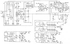
Stefanoo said:this is the pre stage
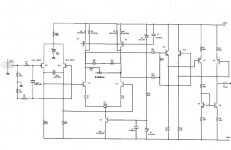
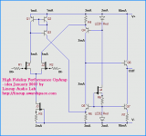
Stefanoo said:and this is the output stage with the protection system,
the bump control and the power supply stage:
Hi, Stefano
1. preamplifier.
Looks like No Global Feedback, with Volume Control
I can not really understand this one.
I am sure I can do better, with not so many transistors.
2. output stage.
Very nice Inverted Power Amplifier.
Looks like it can be very good!
I have saved both figures: preamp + output
I call them:
070122a_preamp.jpg
070122a_output.jpg
They are in my Stefanoo Folder .. in My documents.
See you manyana.
lineup


ok, maybe you don't completely understand feedback..... feedback, especially as it is used in amplifiers, doesn't just reduce distortion, but it sets the overall gain of the amplifier. compensation is used to slow down an amplifier, without compensation you have a large rf oscillator. these are two separate subjects, but they are also somewhat related.....
an amplifier with a differential input stage, even a power amp like this one follows the same rules as an op amp. you have two inputs, inverting and noninverting, and you have an output. there are three basic ways to operate this amp, closed loop with negative feedback, closed loop with positive feedback, and open loop with no feedback.
there are very few applications for operating with positive feedback, and you don't want a 100 watt comparator, so we won't discuss that one. that leaves the negative feedback amp and the open loop amp. we'll go with the open loop amp first. operating the amp open loop, you get whatever gain is present in the amp circuitry, which could be as high as 120db. let's use a 1uV sine wave input signal at 1khz that's .000001V...... at 120db gain that would give us a million volt output, except for a 100 watt amp, we only have +/- 60 volts to work with, so we het a 120V P-P square wave. that's like 99.999% distortion. most preamp outputs have signal levels around .1 to .5 volts, so this amp has way too much gain so how do we get the gain down to a useful level? we could degenerate all of the devices that produce gain in the amp until we have a gain of 30 or so, but it's a very delicate balancing act to match all of the linear regions of all the devices in the chain, and with standard components, you will have mismatches resulting in distortion. so we apply negative feedback to our 120db amplifier. just like with an op amp, we insert a voltage divider at the output, and tap off the desired amount of feedback. let's say we want a voltage gain of 30. so we choose a resistor pair that gives us 1/30 of the input voltage. we'll use 300k and 10k. 300k from output to the inverting input, and 10k from the inverting input to ground. the inverting input will always attempt to maintain itself at the voltage on the noninverting input. so we apply our signal to the noninverting input, and our 120db amp tries to amplify it 120db, but once the voltage fed back to the inverting input goes past what is on the noninverting input, the inverting input "tells" the amp "whoa". so the inverting input limits the output signal so that it tracks the input signal. it tracks the input signal so closely, that if there is any distortion added by the amp circuitry, the inverting input attempts to correct it. so we now have our 120db amplifier "tamed down" to 13.5 or so db, and the inverting input is also correcting for any remaining nonlinearity that it "sees" in the output signal. that's ok for a noninverting amp, but the amp we're looking at in this thread is an inverting amp. almost all of the same rules apply, the inverting input will attempt to maintain itself at the same voltage as the noninverting input. so we now unground the 10k resistor and feed the signal in through it, and ground the noninverting input. the inverting input will now attempt to keep itself at ground, so if the input signal goes positive, it will drive the output negative. the amp is now inverting. if all were perfect with the world, this amp would also have no dc offset, but all is not perfect, there are dc currents flowing in the input elements that will add offset to the output, so we feed back the dc to the input as well to attempt to correct for it as well, but instead of sending it through a voltage divider, we atempt to get all of the dc corrected, so we need a 1:1 ratio of the dc, either on the inverting input (that's the purpose of the existing capacitor,which is now in both the signal path AND the feedback path, or we invert the dc and feed it back on the noninverting input (which is now no longer in the signal path), this is what a dc servo does.
this is getting long, so i'll let you digest this before i describe compensation.........
wow...thanks for the long explanation......as you said i'll digest it and i'll make some questions over as soon as i have reflected enough over those usefull considerations.
I'm looking forward to see the explanations over the compensation!
in the meantime...i was wondering if somebody is interested on make this amplifier and work on it to improve it ........ but it doesn't look like there 's anybody willing to do it!
anyways.....for instance..looking at the different schematics...i'm wondering......is the best choise to use a zener on the input diff stage on the pre to stab the two fet? r there would be something better to employ?
i also have noticed that the power amp almoust uses the same circuit as the preamplifier does.
But in the preamp uses Q4 and Q5 with their bases stabilyzed by the zener D1, instead on the differential stage of the power amp just the resist R23 and r23 are used.
Does anybody know the reason of why? do you think that they did that just to cut off some of the expences
 ??
??
I'm looking forward to see the explanations over the compensation!
in the meantime...i was wondering if somebody is interested on make this amplifier and work on it to improve it ........ but it doesn't look like there 's anybody willing to do it!
anyways.....for instance..looking at the different schematics...i'm wondering......is the best choise to use a zener on the input diff stage on the pre to stab the two fet? r there would be something better to employ?
i also have noticed that the power amp almoust uses the same circuit as the preamplifier does.
But in the preamp uses Q4 and Q5 with their bases stabilyzed by the zener D1, instead on the differential stage of the power amp just the resist R23 and r23 are used.
Does anybody know the reason of why? do you think that they did that just to cut off some of the expences
??
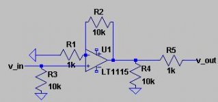
ok, let's start with the input preamp..... i would probably do something like this, with R2 being a volume pot..... power supply rails for the op amp can be anywhere from +/- 6V to +/- 15V.... it's simple and works.
i'm modeling the amp section to see what can be done there.....
i'm modeling the amp section to see what can be done there.....
Attachments
I'm not too fond of a pot in the feedback loop. If the thing fails (which has happenned once with me with an off-board pot) it runs open-loop and goodbye to the speakers.
I also read somewhere from a guy who've experienced issues with reduced pot lifetime if used like this (apparently they start scraping within a few years, even Alps ones) but cannot vouch for it.
That implementation looks fine (after all unclejed is very experienced), but for newbie designs the wrong resistor and pot values with some high-speed opamps can lead to instability too.
I much prefer a dual buffer stage with the pot inbetween to ensure the source driving a high impedance, the pot unloaded and unaffected, and the opamps driving fixed gain. It may be an extra buffer, but worth it for me.
PWatts said:
I much prefer a dual buffer stage with the pot in between
this is how I would do it, too
input buffer - Volume Potentionmeter - output buffer
Op-Amps are not very expensive, in compare to other stuff in an integrated Amplifier
So why not buy 2 Operational Amplifiers
Or a couple of OPA2134, with 2 amps in each device
Or if you want to use your own discrete pre amplifier op-modules
You use my
Lineup Killer JFET amplifier modules!
See here:
New JFET Hifi Op-Amp!
Regards, lineup
Lineup Audio Lab
Attachments
I'm very glad that this 3d is going on .
A couple considerations:
1) since the pre amp is made without feedback network (am i wrong?), why would we consider as improvement the adding of a feedback network?
2) as far as i know, but i could be mistaken by saying this, a discrete stage is way better than a stage made with op amp (speaking of sound) . what do you guys think about this statement?
3) why would you put the potentiometer on the feedback net? what are the advantages of doing this?
A brief consideration on the potentiometer:
A classic ALPS27 costs about $20.
A good potentiometer as TKD could cost about $60
And..a super DACT pot coul reach $150
It's all relative..and depends upon the specific of the potentiometer the precision, reliability and so on.
Of course the prices are very different but the performance are different as well.
I'm personally considering the second one for this project!
.A couple considerations:
1) since the pre amp is made without feedback network (am i wrong?), why would we consider as improvement the adding of a feedback network?
2) as far as i know, but i could be mistaken by saying this, a discrete stage is way better than a stage made with op amp (speaking of sound) . what do you guys think about this statement?
3) why would you put the potentiometer on the feedback net? what are the advantages of doing this?
A brief consideration on the potentiometer:
A classic ALPS27 costs about $20.
A good potentiometer as TKD could cost about $60
And..a super DACT pot coul reach $150
It's all relative..and depends upon the specific of the potentiometer the precision, reliability and so on.
Of course the prices are very different but the performance are different as well.
I'm personally considering the second one for this project!
The preamp of course needs feedback if using opamps with their high open-loop gain. The pot is naturally used to set the gain, and somewhere it should be implemented. In the circuit submitted by unclejed, the gain is set by adjusting the resistor (pot) of the opamp's feedback loop since the gain is determined by G= 1+Rf/Rs, or 1+R2/R1 with R1 being the pot.
However the method preferred by me and lineup is to use two opamps with a fixed gain, say 6dB each, and the pot inbetween them as a simple voltage divider with the top and bottom end connected to output of opamp1 and ground, and wiper to input of opamp 2. Just remember you should use a log pot, but you can approximate a log taper with a lin pot, look at ESP's website for how to do it.
Of course if you're using opamps anyway you can just as well go for the PGA2310 volume control chip, which is basically a digitally controlled OPA2134. You can use a small PIC with a built-in ADC, and then the pot can be a cheap $1 single-channel isolated as far as you like from the analog circuitry. You can even use a cheap motorized pot with remote control. Much better tracking between the two channels too, which may only be beaten by stepped attennuator ones such as DACT. The cost of the PIC and ancillary components, even a small DIY programmer, will still be much less than the TKD pot. Concerning the code it's so damn easy to do, but if you want message me and I'll adapt some of mine for you. I'm building a fully balanced preamp using PGA2310's for a Hypex amplifier (balanced in balanced out) and since the Hypex uses an opamp on the input anyway I see no harm on using opamps in the preamp too. But, I digress.
Concerning discrete vs opamps: unless it's a very good design, few discrete designs can beat some of the newer opamps such as AD8620. Purists hate opamps' high open-loop gain but I for one am happy to use them provided they're properly implemented i.e. only to drive high impedance loads etc.
If you want to go feedback-less or very little feedback with a discrete design that has low open-loop gain, there are many designs on the web and diyAudio.. unless of course you want to try designing one yourself. As simple as they come, the Pass BoSoZ is a nice easy and cheap little one and easy to build, especially if you want balanced in and/or outputs. Sound quality is quite good too.
Nono, it's in the topology. We only need a few dB's of gain for most applications. 24dB for power amps and 12dB for preamps are typical values.
However, most open-loop circuits have higher open-loop gains than this. Feedback (closed-loop) reduces the gain to usable levels. The topology of the circuit used just determines how much feedback, if any, we need to those gain figures.
Some designs have very little open-loop gain, and therefore need no or very little feedback. Others, like opamps, have extremely high open-loop gain, and therefore require lots of feedback to reduce it. Just try to run an opamp open-loop, and you'll quickly see what happens. The ideal opamp gain equation of G = 1 + Rf/Rs becomes infinite when Rf is infinite (open-loop), and distorts horribly since the voltage rails cannot nearly provide enough headroom.

- Status
- This old topic is closed. If you want to reopen this topic, contact a moderator using the "Report Post" button.
- Home
- Amplifiers
- Solid State
- let's start a new project? yeahh!!!