No, this is for balancing mutual inductive influence from rail loops to the loudspeaker wire/trace.
BTW, Dimitri, that little magic pot not only compensates for disturbances induced into speaker wires or traces, but also into other parts of the amp, for example the IPS, which is even more sensitive to (unbalanced) magnetic inductions from the supply leads (or traces).
Cheers,
E.
Alt-ETMC
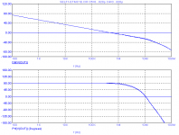
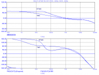
I forgot to drop the gain and phase response of the global FB loop (via R7, 1st pic) respectively local FB loop (via node A, 2nd pic). Finally, here they are.
Regarding the global loop response, notice that opposed to the previous example, the gain and phase bubble around 1MHz has gone.
Cheers,
E.
I forgot to drop the gain and phase response of the global FB loop (via R7, 1st pic) respectively local FB loop (via node A, 2nd pic). Finally, here they are.
Regarding the global loop response, notice that opposed to the previous example, the gain and phase bubble around 1MHz has gone.
Cheers,
E.
Attachments
>What about tying the collector of the Q5 ....
What about deleting Q5 altogether?
Here's an alternative approach of ETMC, courtesy of Dimitri who co-invented this mod.
All 'unnecessary' connections to gnd have been eliminated, except R9, as this one has to be tied to gnd.
As for the positive FB loop, now the signal is taken directly from the VAS emitter and fed to the emitter of Q2. This mod saves one tranny, though at the cost of two more C's and R's ....
Ho ho ho, this is very nice. I like it, really.

Yes, nice work both methods are impressive!
Absolutely!!
 I tried TMC/ETMC variants on both my symasym based design and my "blameless". On the blameless I observed a 10X reduction of total THD (300 to 30ppm) , most of which appeared to be higher order harmonics. Ported to my *sym ,the differences were more subtle .. but I did LOVE the substantial reduction of H5/7/9/11 (almost gone -142/-145/-150db!!). It is almost as through the BJT OP stage's Xover distortion influence was fully negated. The only way I could get the second FFT (below) before TMC/ETMC was to run the circuit in isolation (no OPS). I must be doing it right ,as my closed loop plot shows sufficient margin way after the UG point. I LIKE it... thanks Edmond..
BTW , I am not using as many "ideal" sources , so my results may not be single digit PPM. I also am not seeking PPM , but low high order components.
OS
Attachments
Last edited:
Thanks Edmond for the link on the P1 pot.
Unfortunately DIYAudio seems to have lost all the schematics back there, looks like for the whole thread from a few random checks. But the explanation clears things up. Obviously the induced currents and causative currents are in phase and can be cancelled directly. I was just instinctively thinking of inductive coupling with a 90 degree phase shift, but these are 0 degree transformer like currents. So this pot should be able to correct gm mismatches between N and P sides as well I take it. The final comment about a second pot:
"PS: For a more precise compensation, actually, you need two pots."
Would this happen to be like the P2 pot I mentioned above? (between the P1 wiper and the OUT terminal) So as to adjust the magnitude of the current feedback.
I'm hoping to apply the crossover current feedback scheme to a push-pull tube amplifier (class AB mode) using local plate feedbacks. This would use sense resistors above the tube plates (to the output transformer) and resistive feedbacks from the plates back to a differential driver stage.
Don B.
No, this is for balancing mutual inductive influence from rail loops to the loudspeaker wire/trace.
Dimitri! We could have talked about this while we had coffee together at AES!
You should have told me!
jan didden
You didn't askYou should have told me!
 and this is work in progress...
Last edited:
Absolutely!!
[snip]
OS
Hi Pete,
Glad to hear about your encouraging results. The more so as in the past, not everybody was equally successful.
Cheers,
E.
trim-pot, distortion #6
Hi Don,
That's right. The old schematics are lost, for some reason.
Perhaps, they are vanished into the sin-bin.
Hope you don't mind, but I have to correct your interpretation. Because of the phase relationship, the trim-pot does not compensate for gm mismatches, only for magnetically induced voltages from the supply rails. This is because the induced voltage leads the current by 90 degrees and also increases with frequency. The crux is that the compensating error voltage from the trim-pot is fed back via a capacitor (C7). So the resultant current through this cap also leads the error voltage by 90 degrees (and also rises with frequency). As a result, the final correction signal is again in phase with current through the supply leads.
So, for compensation of gm mismatches, we need another trim-pot.
In the past, I also did some sims with two pots, but it seems to make sense only if one strives for ultra low distortion, far below 1ppm.
Cheers,
E.
Thanks Edmond for the link on the P1 pot.
Unfortunately DIYAudio seems to have lost all the schematics back there, looks like for the whole thread from a few random checks.
Hi Don,
That's right. The old schematics are lost, for some reason.
Perhaps, they are vanished into the sin-bin.
But the explanation clears things up. Obviously the induced currents and causative currents are in phase and can be canceled directly. I was just instinctively thinking of inductive coupling with a 90 degree phase shift, but these are 0 degree transformer like currents. So this pot should be able to correct gm mismatches between N and P sides as well I take it. The final comment about a second pot:
Hope you don't mind, but I have to correct your interpretation. Because of the phase relationship, the trim-pot does not compensate for gm mismatches, only for magnetically induced voltages from the supply rails. This is because the induced voltage leads the current by 90 degrees and also increases with frequency. The crux is that the compensating error voltage from the trim-pot is fed back via a capacitor (C7). So the resultant current through this cap also leads the error voltage by 90 degrees (and also rises with frequency). As a result, the final correction signal is again in phase with current through the supply leads.
So, for compensation of gm mismatches, we need another trim-pot.
"PS: For a more precise compensation, actually, you need two pots."
Would this happen to be like the P2 pot I mentioned above? (between the P1 wiper and the OUT terminal) So as to adjust the magnitude of the current feedback.
I'm hoping to apply the crossover current feedback scheme to a push-pull tube amplifier (class AB mode) using local plate feedbacks. This would use sense resistors above the tube plates (to the output transformer) and resistive feedbacks from the plates back to a differential driver stage.
Don B.
In the past, I also did some sims with two pots, but it seems to make sense only if one strives for ultra low distortion, far below 1ppm.
Cheers,
E.
Dimitri! We could have talked about this while we had coffee together at AES!
You should have told me!
jan didden
Huh?
 Why?
Why?Huh?
Well it is very seldom that you have the pleasure to discuss these things face-to-face. I would have enjoyed it.
But it was anyway nice to chat with Dimitri
jan didden
By E. Stuart - In the past, I also did some sims with two pots, but it seems to make sense only if one strives for ultra low distortion, far below 1ppm.
Some seem to only strive for ultra low innovation.
I am honoured to actually see some ppm readings myself (below) , even with a crude LT representation. My mention of even TMC brought forth the reference of an oscillator "dead fish" , confirming my first statement. THD 20 was actually 50ppm , and that is on a DX amp (BX).. absolutely amazing. 1 PPM ...why not? , even as we know that might be impossible in the real world (layout/inductances/parasitics). OS
Attachments
Re; Edmond:
"This is because the induced voltage leads the current by 90 degrees and also increases with frequency. "
Ah, I had missed the voltage to current part. THX.
"So, for compensation of gm mismatches, we need another trim-pot."
Like maybe a resistive path around the TMC network? Seems like that would kill the VAS loop gain. So some phase fixup maybe before going thru the TMC?
"In the past, I also did some sims with two pots, but it seems to make sense only if one strives for ultra low distortion, far below 1ppm"
Interesting, I would have thought that varying the output degeneration resistors would have caused large effects on this feedback, but I guess the effective transconductances co-vary too.
"That's right. The old schematics are lost, for some reason."
I hope there is some chance of that being fixed. An incredibly rich resource got the axe there. That Wayback Machine or something maybe? Google Cache? Surely DIYAudio kept a backup? Perhaps they need to implement a daily burn to DVD.
Don B.
Last edited:
Some seem to only strive for ultra low innovation.
OS
Hi Ostripper,
These numbers are really, really impressive, but how do the numbers look with a 20 kHz fundamental?
Cheers,
Bob
Hi Ostripper,
These numbers are really, really impressive, but how do the numbers look with a 20 kHz fundamental?
Cheers,
Bob
63ppm @ 40vpp /110ppm @90vpp - 20khz. I always thought of TMC in the terms of the "Self way" and was not impressed. With that little example of Edmonds ..Wahzooo! I then added the ETMC which had a much smaller effect on total THD. ETMC's beneficial attributes were noticable with "garbage" on the rails (PSRR) , improper OPS biasing.
I used Carlos's little amp since it is so "blameless" (below) and I actually have a pair running my 200W OPS's presently. Perfect test pig... The (2nd pix) shows JUST the TMC closed loop , when I first saw this I was a bit worried. It seems as if TMC extends the available loop gain to a higher frequency allowing better correction at those frequencies. The global closed loop bode(pix 3) is what convinced me to actually get out the soldering iron. Seems my phase margin was pushed to even higher frequencies ...
BTW ,is 120ppm THD20 really that bad ?? (pix4) .. this is just simulation, the real amp did not burn or oscillate , even with dubious used TV silver mica's.
OS
Attachments
Last edited:
"That's right. The old schematics are lost, for some reason."
I hope there is some chance of that being fixed. An incredibly rich resource got the axe there.
Can someone provide links to the posts? Maybe we can find the missing info.
Unfortunately DIYAudio seems to have lost all the schematics back there, looks like for the whole thread from a few random checks.
Hi Don,
That's right. The old schematics are lost, for some reason.
Can you provide some examples. I went thru the 1st 500 posts and then random after that and could not find any missing attachments.
dave

I see Pano beat me...
RE: missing attachments
Are you looking in the right thread:
"Bob Cordell Interview: BJT vs. MOSFET"
Try post 1194 there:
http://www.diyaudio.com/forums/soli...-interview-bjt-vs-mosfet-120.html#post1207199
I would try to figure out the range, but I can barely stay awake at the moment here.
Are you looking in the right thread:
"Bob Cordell Interview: BJT vs. MOSFET"
Try post 1194 there:
http://www.diyaudio.com/forums/soli...-interview-bjt-vs-mosfet-120.html#post1207199
I would try to figure out the range, but I can barely stay awake at the moment here.
Last edited:
- Home
- Amplifiers
- Solid State
- Bob Cordell Interview: Negative Feedback