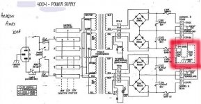
I have been researching the topic of multiple bridges in the power supply for my amplifier project. Most of the schematics I've seen float the gnd completely. I've seen other mainstream amps that actually tie to chassis gnd thru a low value, high wattage resistor, see my attached schematic of an Aragon PS. Mondial is using 4 bridges on dual secondaries but tied to chassis gnd thru a couple of low value high wattage resistors. Which is the better way of doing it or is it a subjective thing?
Attachments
The idea of tying chassis ground (mains earth) to 0V is for safety should the primary/secondary insulation in the transformer break down. The resistors are to prevent a ground loop forming.
http://sound.westhost.com/earthing.htm explains it more.
Multiple bridges doesn't really make a difference.
http://sound.westhost.com/earthing.htm explains it more.
Multiple bridges doesn't really make a difference.
Chamberman said:I have been researching the topic of multiple bridges in the power supply for my amplifier project. Most of the schematics I've seen float the gnd completely. I've seen other mainstream amps that actually tie to chassis gnd thru a low value, high wattage resistor, see my attached schematic of an Aragon PS. Mondial is using 4 bridges on dual secondaries but tied to chassis gnd thru a couple of low value high wattage resistors. Which is the better way of doing it or is it a subjective thing?
Multiple bridge as viewable from your schematic are useful when common main transformer are employed in order to decouple circuit ground from the main, which may capacitively conduct nuisances and form high frequency (ultrasonic) loops. This because, with multiple bridges, even the internal ground of equipment "see" the tranformer only when diodes are conducting. The trick is less useful when an insulation (or safety) main transformer is employed.
The odd of this kind of connection is that require separate pair of secondary windings for each channel. If only a single pair of windings is available for either channels then you must use traditional connections of them using a single bridge for a dual supply (which, however may be individual for each channel).
Hi
Piercarlo
 Duh! Guess I should pay better attention...
Hi,
the previous posters have given the correct information, but I consider it important enough to be worth summarising and taking the discussion on a little further.
For good audio, the audio ground should float. The amplifier as a music reproducer will work very well like this.
For safety ALL exposed conductive parts MUST be earthed.
The only exception is doubled insulated equipment that meets the required double insulated standard.
To meet that second requirement the audio ground must be connected to the safety ground. When this is done the noise on the safety earth contaminates the audio ground and the amplifier transfers this to the speaker on the output.
The solution is to insert a disconnecting network between audio ground and safety earth.
This, unfortunately, causes a problem for fusing the unit to a safe standard.
Let's look at the schematic in post1.
The two Rs connecting each audio ground to safety earth are 10r 5W. If a fault current through either of these resistors flows to earth then a big voltage and heat are developed across the affected resistor. If 10A flows to earth and the fuse blows then all is well and good. If the fuse does not blow then 100V appears on the live parts (RCAs or speaker return terminal). The resistor now heats up due to a dissipation of 1kW. It will burn out within a few mS. Now the RCAs or the speaker terminal could have full mains voltage on them. The resistance in the earth wire in the cable back to the distribution board will raise the chassis voltage (the UK limit is about 50Vac) as well.
Now I asked you to look at a constant 10A fault current flowing to earth and we saw the dangerous position the unit can/will fail to.
In real life the situation is even worse.
A fuse can carry rated current for hours and even days before breaking. At the other extreme the same fuse can carry thousands of Amps for fraction of mS before breaking.
The resistors connecting audio ground to safety ground MUST SURVIVE LONGER than the fuse at any fault current value that flows to earth. Some resistors may not meet this requirement! Do you want to test your installation?
I suggest you fit something in parallel with the resistor that WILL SURVIVE LONGER than the fuse.
some of the suggestions are:-
power diodes, connected in inverse parallel,
power thermistor
Do not take safety lightly.
- Status
- This old topic is closed. If you want to reopen this topic, contact a moderator using the "Report Post" button.
- Home
- Amplifiers
- Solid State
- Multiple bridge PS, floating gnd question