I have a yamaha m-50 I am trying to repair, anatec has been helping me on another forum (and instrumental in me getting as far as i have!) and suggested i post up here as well, so ill post up its problems, and what ive tried, and see if anyone has any other ideas!
the problem is as follows
-protection clicks on when the levels are turn above 4
-happens regardless of input level/type (input is via a htpc)
-test on 3 different sets of speakers, same result
-amp is drawing approximately .5 amps of power when in use, the same amount of power my other 4 amps are pulling combined (m-80, m-45, fosgate m100)
i have replaced a cap in the protection circuit (c-145), which had no affect. i then proceeded to try and calibrate it based on the service manual
here is the calibration chart from the manual
http://miniunit.com/user_uploads/Zorac/m-50_calibration.jpg
with an input of 118.8v i had 62.1v (suppose to be 65.5) for step one, and 2.8v (suppose to be 1.0) for step two.
adjusting vr601 had negligible effect, so i left it in the middle, adjusting vr602 had a very small effect, the original reading was 3.2v for step two and by adjusting it all the way down i could only obtain the 2.8v
i then proceeded to use the power trouble shooting page from the manual, although i dont have a variac, i was able to do some of the tests
here is the testing procedures:
http://miniunit.com/user_uploads/Zorac/powerdiagnose.jpg
for the first procedure they gave a reference for 120vac (which should give a reading of 5.5vac and i measured 8.7vac on my amp with input voltage being 120.2vac) and the second procedure is the same as the second calibration step, which i already knew is reading way high.
as i understand, in these circuits, the electrolytic caps are generally the first thing to go, and being only two of them, ill replace them, and with the first trouble shooting procedure indicating a problem, ill replace the src/triac/control ic as well.
for reference, the power control circuit
http://miniunit.com/user_uploads/Zorac/control_board.jpg
i am working on access to a variac so that i may probably perform the troubleshooting procedure.
i would appreciate any ideas/help/procedures to help me narrow down the problem!!
keep in mine, although im comfortable working on the amp, know what all the basic components do, i have no clue when i come to interpreting a circuit.
thanks!
Try to hook up with no load at first to see if you get the same result.Then load up one channel at a time to see if we can isolate the left or right channel.
For reference a M-45 has two 22,000 ufd @ 71vdc -yamaha p/n V6512400 in the power supply thru Yamaha they are around $30 ea.
Dave
For reference a M-45 has two 22,000 ufd @ 71vdc -yamaha p/n V6512400 in the power supply thru Yamaha they are around $30 ea.
Dave
Yes I was refering to the speakers,If you have a signal generator 1khz input will work . If no generator, any sound source will do.
The only monitoring required is your ears.What I was going for was to try and determine 1.) If the protect engages with no speakers hooked up. 2.) Engages with either the Rt or the Lt. You stated that turning the volume up beyond 4 and the protect engages....So with no speakers attached turn the volume up beyond 4 and so on with a speaker on one channel and then the other. The protect circuit may or my not be operating correctly.")
Dave
P.S. If possible could I get a copy of the schematic. The closest I have is a M-45 and judging by your already posted partial diagrams it is way different.Especially the power supply.
The only monitoring required is your ears.What I was going for was to try and determine 1.) If the protect engages with no speakers hooked up. 2.) Engages with either the Rt or the Lt. You stated that turning the volume up beyond 4 and the protect engages....So with no speakers attached turn the volume up beyond 4 and so on with a speaker on one channel and then the other. The protect circuit may or my not be operating correctly.
Dave
P.S. If possible could I get a copy of the schematic. The closest I have is a M-45 and judging by your already posted partial diagrams it is way different.Especially the power supply.
i know it will do it with no load, thats first thing i check, as a blown speaker would do this, so i unplugged the speakers and had the same result, i will test further to see if changing where the input is applied (l or r) has an affect.
edit:
i did some further testing, it doesnt not seem to be left or right related.
with a signal (input) on both l and r, and a load on l, r, both, or neither results in the protection coming on.
with a signal on the l input only, and a load on the l only speaker, the protection wont come on. with a signal on the r input only, and a load on the r only speaker, the protection wont come on.
here are the schematic, be warned, its about 100mb for all 3
http://miniunit.com/user_uploads/Zorac/Yamaha M-50 SM Pg 12.JPG
http://miniunit.com/user_uploads/Zorac/Yamaha M-50 SM Pg 13.JPG
http://miniunit.com/user_uploads/Zorac/Yamaha M-50 SM Pg 14.JPG
http://miniunit.com/user_uploads/Zorac/Yamaha M-50 SM Pg 12.JPG
http://miniunit.com/user_uploads/Zorac/Yamaha M-50 SM Pg 13.JPG
http://miniunit.com/user_uploads/Zorac/Yamaha M-50 SM Pg 14.JPG
Zorac
I can not open the last of the schematic files
http://miniunit.com/user_uploads/Zo...M Pg 14.JPG
can you? Does it have the actual schematic
This is interesting
Dave
I can not open the last of the schematic files
http://miniunit.com/user_uploads/Zo...M Pg 14.JPG
can you? Does it have the actual schematic
This is interesting
...Do you get good audio sound or is it distorted? Any leads on a variac?with a signal on the l input only, and a load on the l only speaker, the protection wont come on. with a signal on the r input only, and a load on the r only speaker, the protection wont come on.
Dave
try opening it in 'windows picture and fax viewer' (you can get to it in winxp by doing a right click on the file and selecting preview). i know alot of other programs dont like it due to the size. the full size is 56.0 MB (58,792,934 bytes) for pg 14. pg 14 is the full schematic. i checked my server, and its all there.
no variac yet. the guy who i though might have access to one, turns out they dont have one in their shop. so im watching ebay, cheap ones without a case go for fairly cheap. wouldnt take much to wire one up and build a case.
the audio when testing one side at a time was clear, i wasnt listening specifically for distortion, but i didnt hear any either. i would of noticed though if there was any appreciable amount.
mikeks said:Zorac, it would be helpful if you reduced the size of the schematic by saving, say, as .png.
not as easy to read, but waaaaay smaller as requested:
http://miniunit.com/user_uploads/Zorac/yamaha m-50 sm pg 12 small.jpg
http://miniunit.com/user_uploads/Zorac/yamaha m-50 sm pg 13 small.jpg
http://miniunit.com/user_uploads/Zorac/yamaha m-50 sm pg 14 small.jpg
danielm said:Any DC on the outputs?
Any AC on the outputs with no input?
Do you have a scope?
Anything getting warm?
there was a little dc voltage, but that was easliy adjusted out by the dc offset adjusters
there was a little ac, but then the meter always seems to read a little (in the couple mV range)
no scope
nothing gets warmer than it should.
Zorac said:
there was a little dc voltage, but that was easliy adjusted out by the dc offset adjusters
Good.
there was a little ac, but then the meter always seems to read a little (in the couple mV range)
Does it go to zero when the amp is turned off? Might have to short the leads.
no scope
Darn.
nothing gets warmer than it should.
Thats good.
I can't help but think it is oscillating. Which you might be able to see on the ac meter. But, I imagine it is a frquency above what the meter can measure. A scope would be nice for this.
danielm said:
Thats good.
I can't help but think it is oscillating. Which you might be able to see on the ac meter. But, I imagine it is a frquency above what the meter can measure. A scope would be nice for this.
based on that suggestion, i tried using the meter on hz mode just to see what would happen and observed the following:
- the meter in the middle of the room read 0hz
- the meter in vicinity of the amp, on or off read 60hz
- the meter connected to the speaker output with no input to the amp and the amp on read 0hz
- the meter connected to the speaker output with no input to the amp and the amp off read 60hz
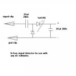
here's a high frequency signal detector. you hook it up to your DC voltmeter, and it will detect the presence of high frequency signals like oscillation or RF. it will not tell you the frequency, and the voltage reading is the peak value (NOT RMS!!!), but it will indicate whether or not something is there. it will also indicate audio signals about 1khz and above, so if you're checking for oscillation, you might want to use a 100hz or lower test signal.
Attachments
thanks for the diagram unclejed! i ll have to pick up the parts to give that a try!!! i have a couple other suggestions for parts (some suspect electrolitc caps in the control circuit) to replace which i need to pick up too, to bad its next to impossible to get to the store!! (they are only open during work hours, and on top of that, i have to drive to the city to get there as i live in a neighbouring town)
i have done some more testing though based on the recommendation of others, and here are the results, maybe it'll give one of you guys some ideas!!
i was asked to check the resistance across some transistors (with the amp off and unplugged) and found this:
-the drive transistors can be unplugged, which resulted in easy readings, and all the resistance matched up (when compared left channel to right channel)
-power transistors were harder to read, as the reading seem to drift (i assume because they were still in the circuit), but they all seem close. ranges of resistance were in the 1 to 2 M ohm range.
i was asked to check the voltage across some other transistors and found this:
http://miniunit.com/user_uploads/Zorac/m-50 test.xls
- Status
- This old topic is closed. If you want to reopen this topic, contact a moderator using the "Report Post" button.
- Home
- Amplifiers
- Solid State
- yamaha m-50 repair