Here's my small contribution to the audio DIY world...
It's basically a combination of the LM4702C driver with the LT1166 power output stage biasing system, replacing the QMult in the original LM4702 application note. Arrownac sells the LT1166 sells for about $2, well worth replacing the QMult, as long as the impact on AC performance is kept to a minimum by bypassing the Gm stage.
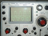
At Vc=+/-44V the breadboarded version has a bandwidth of 28KHz (0.1dB), Distortions at f=20KHz and Po=87W (just before clipping), were unmeasurable using my rudimentary TI UAF42 based notch filter which, based on previous measurements, makes them better than 0.01%.
Clipping occurs at Vo(peak) = 39V and is clean and symmetrical. For a 4ohm load, clipping occurs at Po=150W and is because of the output Darlingtons base current, which is larger than the 5mA that the LM4702 can provide. Triplets are required to further push the output power (this was not experimented so far).
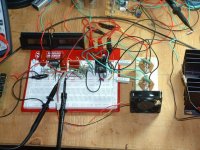
Schematic is attached, I'll follow up with some pictures.
Planning to design the PCB ASAP...
It's basically a combination of the LM4702C driver with the LT1166 power output stage biasing system, replacing the QMult in the original LM4702 application note. Arrownac sells the LT1166 sells for about $2, well worth replacing the QMult, as long as the impact on AC performance is kept to a minimum by bypassing the Gm stage.
At Vc=+/-44V the breadboarded version has a bandwidth of 28KHz (0.1dB), Distortions at f=20KHz and Po=87W (just before clipping), were unmeasurable using my rudimentary TI UAF42 based notch filter which, based on previous measurements, makes them better than 0.01%.
Clipping occurs at Vo(peak) = 39V and is clean and symmetrical. For a 4ohm load, clipping occurs at Po=150W and is because of the output Darlingtons base current, which is larger than the 5mA that the LM4702 can provide. Triplets are required to further push the output power (this was not experimented so far).
Schematic is attached, I'll follow up with some pictures.
Planning to design the PCB ASAP...
Attachments
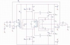
D1 and D2 give the LT1166 some voltage headroom. Look up the chip on www.linear.com. They won't be absolutely necessary with a triple darlington.
Try taking out R11, I bet it will still work just fine.
If it does, then Q1,2,3,4 and associated parts are not needed.
These parts are in the application note because they need to provide the voltage drop across the bias IC. The LM4702 sources the current from pin 2, and then sinks it into its own internal CCS on pin 3.
I would recommend you slap a cap from pin 2 to pin 3 of the LM4702, try 1µF~100µF.
I would also do a triple as the LM4702 has very low output current.
The LM4702 can provide only 5mA of output current. That's definitely not enough to both bias the LT1166 (min +/-4mA at +/-2V) and provide the base current for the output darlingtons. Therefore, some extra current is required to bias the LT1166 and that's the purpose of the current sources. They could be replaced by simple resistors to the +/- supplies, however this will negatively impact the PSRR. The LT1166 PSSR is only 19dB...
djk said:
I would recommend you slap a cap from pin 2 to pin 3 of the LM4702, try 1µF~100µF.
Could you elaborate on this? A couple of hundreds of pF to ground from each output could be a frequency compensation method (but then the LM4702 gain stage is already compensated). Experimentally, for 500pF the SR is seriously affected, but for 1uF-100uF...?!
"Could you elaborate on this? A couple of hundreds of pF to ground from each output could be a frequency compensation method (but then the LM4702 gain stage is already compensated). Experimentally, for 500pF the SR is seriously affected, but for 1uF-100uF...?!"
My thinking is that 100µF across pin 2 and 3 of the LM4702 would prevent the AC signal from modulating the DC drop generated by the LT1166.
My thinking is that 100µF across pin 2 and 3 of the LM4702 would prevent the AC signal from modulating the DC drop generated by the LT1166.
syn08 said:Here's my small contribution to the audio DIY world...
As suggested by other, substitute the 1N4001 diodi with transistor (coming to a triple darlington) or, may be better, remove diodes and driver transistor and substistute they with power complementary MOS. LT1166 was originaly designed for biasing MOS output stages (which aren't well thermal tracked by usual VBE multipliers) and stabilize their quiescent current.
With this arrangement you should overcome the problems of poor LT1166 biasing (MOS turn-on gate drive are high enough to guarantee correct voltage supply) and in the same time that of limited output current capabilities of LM4702.
Hi
Piercarlo
syn08 said:Here's my small contribution to the audio DIY world...
It's basically a combination of the LM4702C driver with the LT1166 power output stage biasing system
-------------------------------
At Vc=+/-44V the breadboarded version has a bandwidth of 28KHz (0.1dB),
Distortions at f=20KHz and Po=87W (just before clipping), were unmeasurable
.... makes them better than 0.01%.
-----------------------------
Planning to design the PCB ASAP...
Thanks, syn08.
I say thanks not so much for my own sake,
but it is not unusual people ask here for
an easy way to get High Power Output.
(With no other advice given, than: Use less power! or Go build a real High Power discrete amplifier)
This is something to make this possible!
In a sort of standardisized way, using 2 IC and a few Output Transistors.
I hope there will be several followers with similar circuits
in Chip Amps forum.
I am sure will be .......
thanks again, for an original idea

because, speaking of me only, it is first time I see this
And no lie: I have seen a lot of amplifiers before
... now keep on doing the rest
... improvements, practical PCB etc
... prototyping
... trimming for best performance
... new PCB version
... a bit of basic documentation
Well, you know all these routines of a good amplifier project, syn08
Regards
lineup
syn08 said:
For a 4ohm load, clipping occurs at Po=150W and is because of the output Darlingtons base current,
which is larger than the 5mA that the LM4702 can provide.
Triplets are required to further push the output power (this was not experimented so far).
Before you try Triple Darlington,
try with some replacement, if possible, for TO-220 MJE15030/31 drivers
We have some TO-126 for example, with higher gain (less base current).
I am thinking first hand of BD139/140 and for higher voltage than 80
we have MJE340 / MJE350.
I am sure there are some other, as well, that may have a bit higher gain than MJE15030 / MJE15031.
-----------------------------------------------------
Another way is to try Power transistors with higher gain than MJ21193/94.
For example some of:
MJL0281A-MJL0302A
MJL3281A-MJL1302A
MJL4281A-MJL4302A
http://www.onsemi.com/pub/Collateral/MJL4281A-D.PDF
Search and sort by Parameter hFE gain
Here at www.onsemi.com
OnSemi.com - Bipolar Audio Transistors - Parametric Table
lineup
Re: Re: My small contribution
Again, using darlington triplets is doable and this would indeed eliminate the need for diodes. I'm personally not a big fan of triplets, I had stability issues in the past and the solution was a zero at a frequency to give a gain of 1 in the VAS before the phase of the triplets degenerate the stability of the loop. Not much fun! OTOH, triplets are required only for high power in 4ohm loads. Otherwise, the diodes are always ford biased and their ac contribution is close to nothing.
Unfortunately, using cheap power MOSFETs is not an option. The LM4702 has a max differential output voltage of 6V. This would not cover the Vgs required by the complementary power MOSFETs (about 4-5V each). Logic level MOSFETs would be required, but those are not that common/cheap.
Piercarlo said:
As suggested by other, substitute the 1N4001 diodi with transistor (coming to a triple darlington) or, may be better, remove diodes and driver transistor and substistute they with power complementary MOS. LT1166 was originaly designed for biasing MOS output stages (which aren't well thermal tracked by usual VBE multipliers) and stabilize their quiescent current.
With this arrangement you should overcome the problems of poor LT1166 biasing (MOS turn-on gate drive are high enough to guarantee correct voltage supply) and in the same time that of limited output current capabilities of LM4702.
Hi
Piercarlo
Again, using darlington triplets is doable and this would indeed eliminate the need for diodes. I'm personally not a big fan of triplets, I had stability issues in the past and the solution was a zero at a frequency to give a gain of 1 in the VAS before the phase of the triplets degenerate the stability of the loop. Not much fun! OTOH, triplets are required only for high power in 4ohm loads. Otherwise, the diodes are always ford biased and their ac contribution is close to nothing.
Unfortunately, using cheap power MOSFETs is not an option. The LM4702 has a max differential output voltage of 6V. This would not cover the Vgs required by the complementary power MOSFETs (about 4-5V each). Logic level MOSFETs would be required, but those are not that common/cheap.
Re: Re: Re: My small contribution
In another topic, jackinnj has managed to use LM4702 with MOSFETS.
He has got homepage http://tech-diy.com/
Think he used Lateral MOSFETs, in the other LM4702 topic, in Chip Amps.
They have lower Vgs. Like ~1.0V
You find a lots of LM4702 stuff, in this dedicated page:
http://www.werple.net.au/~gnb/audio/lm4702.html
But I am sure you already know most of this info.
lineup
syn08 said:
Unfortunately, using cheap power MOSFETs is not an option. The LM4702 has a max differential output voltage of 6V. This would not cover the Vgs required by the complementary power MOSFETs (about 4-5V each). Logic level MOSFETs would be required, but those are not that common/cheap.
In another topic, jackinnj has managed to use LM4702 with MOSFETS.
He has got homepage http://tech-diy.com/
Think he used Lateral MOSFETs, in the other LM4702 topic, in Chip Amps.
They have lower Vgs. Like ~1.0V
You find a lots of LM4702 stuff, in this dedicated page:
http://www.werple.net.au/~gnb/audio/lm4702.html
But I am sure you already know most of this info.
lineup
- Status
- This old topic is closed. If you want to reopen this topic, contact a moderator using the "Report Post" button.
- Home
- Amplifiers
- Solid State
- My small contribution