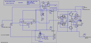
ok, i've solved the instability problem and also quite by accident cleaned up the clipping behavior. i was going to post this with the question "how do i fix the instability in this amp? i had this design "working", but to keep it stable, i had to use an integration cap in the feedback loop, which while it worked, is bad practice, since it leaves the amp susceptible to oscillation at higher frequencies, and is an RF interference problem waiting to happen. i knew i had to limit the gain bandwidth product somehow, and dominant pole compensation just lowered the oscillation frequency. i was reading leach's description of his input stage, and although i can't add resistance to the emitters of the diff amp to limit GBW, (this design uses an op amp input stage), i could apply local feedback to the op amp. so i began by adding R7 and setting it at 100k, which would set the op amp gain at 100..... no change, so i began lowering it in a 5,2,1 sequence until i noticed any changes in overall gain. at first the gain didn't seem to change, until i got down to 2k...... hmm..... so i tried 1k..... the output went from 130vp-p to a clipped 198vp-p..... interesting.... the gain reduction of the op amp was beginning to increase the overall gain because the global feedback has less effect. but in the meantime i noticed that not only was the instability problem cured, but the clipping behavior had improved. there is no longer any clipping "hangover" (an appropriate term, since it would give you a headache listening to an amp that does it). i will begin going back up incrementally with the op amp gain to see what the tradeoffs are, but this looks like it could be a good sounding design. the zener is my "bias shortcut" and will be replaced by a real Vbe multiplier when i prototype this amp......
i was going to add a predriver stage with a Baker clamp to clean up the clipping, but it looks like i don't have to
i was going to add a predriver stage with a Baker clamp to clean up the clipping, but it looks like i don't have to
Attachments
Hi Uncle,
have you read W Jung's composite opamps?
In effect he says the gain of the buffer be limited by an internal feedback loop and this then limits the gain of the global loop to about 2 times more. A small feedback cap between the two stages can be added.
Your power amp is very similar and I suspect may respond to exactly the same rules.
http://waltjung.org/PDFs/ADI_1992_Seminar_Audio.pdf
http://waltjung.org/PDFs/Composite_Line_Driver_with_Low_Distortion.pdf
tnx..... i think that the instability problem was actually the op amp and the VAS competing for gain and feedback. what i mean is that both had such high gain and only one feedback path, that the op amp and the VAS couldn't "decide" which one was producing the voltage gain. there is also the possibility that i was running the VAS at the edge of it's linear region, so much so, that it was difficult to control distortion with feedback, and when the amp clipped, the VAS was intensely saturated. using local feedback in the input amp seems to have cured "all of the above" problems. i designed this as a simple amp, but the instability in the simple design had me beginning to think that i may have to add more complexity to the design to tame the various quirks of the design. for instance, i was going to add another buffer stage with a Baker clamp to take care of the "hangover" (now that i see where the problem stemmed from, the clamp probably wouldn't have helped much). the only actual added complexity that i really wanted here was the DC servo and the clipping indicator. i checked the THD of the design again after i posted the first message, and the distortion improved another 10db. with that accomplished, i can move on to "fudging" the component specs to see what will happen to the distortion figures, etc... with real components, like 5% tolerance resistors, transistor pairs with one with more or less gain or junction capacitance than the other, etc...
i'm glad that the solution to the problems in this simple design was the addition of one resistor.....
i'm glad that the solution to the problems in this simple design was the addition of one resistor.....
- Status
- This old topic is closed. If you want to reopen this topic, contact a moderator using the "Report Post" button.