Hello,
I'm going to make AV400 amplifier with self-routed PCB.
I want to decrease power supply voltage to about +-56VDC. How many watts I will have with +-56VDC. Does I need to change any values in schematics for lower voltage and what is the lower working voltage for AV400?
How many OP pairs I need with lower voltage? Or does it better to use 4 pairs anyway?
Does it legal to post a schematics (redraved by me) of AV400?
Hi Stanley
The AV400 will work just fine on 56 volts I would only use 2 x pairs of Mosfets that is all you would require at that supply voltage.
Power out into 8 Ohms will be around 120 watts or so and into 4 Ohms about 200. the later will depend on your supply regulation.
Post a way your schematic its OK....")
The AV400 will work just fine on 56 volts I would only use 2 x pairs of Mosfets that is all you would require at that supply voltage.
Power out into 8 Ohms will be around 120 watts or so and into 4 Ohms about 200. the later will depend on your supply regulation.
Post a way your schematic its OK....
Hello,
thanks for answers
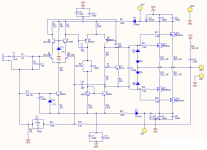
Here is my modified schematics:
- added a pair of snubber MKT capacitors
- removed clipping detector
- fuses are on power supply board
- does it needed to add these networks to output with inductor and resistor in parallel and capacitor and resistor in series? And what values they must be?
In AV800 schematics there are 2 diodes with zenners in gate protection circuit, does it needed to put this diodes to AV400? And what is their purpose?
Schematics:
Poweramp.pdf
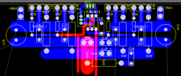
And PCB:
What you think about that way of routing OP part.
The PCB will be double sided. What you could suggest to change in that PCB?
thanks for answers
Here is my modified schematics:
- added a pair of snubber MKT capacitors
- removed clipping detector
- fuses are on power supply board
- does it needed to add these networks to output with inductor and resistor in parallel and capacitor and resistor in series? And what values they must be?
In AV800 schematics there are 2 diodes with zenners in gate protection circuit, does it needed to put this diodes to AV400? And what is their purpose?
Schematics:
Poweramp.pdf
And PCB:
What you think about that way of routing OP part.
The PCB will be double sided. What you could suggest to change in that PCB?
An externally hosted image should be here but it was not working when we last tested it.
Attachments
... no , its not necessary to use heatsink in this project for Q6,Q7,Q8,Q9 except finals MOSFET-s http://i14.tinypic.com/29ct3sk.jpg
http://i14.tinypic.com/29ct3sk.jpgTo alex mm:
What are these things that you use like zenners that look like tiny coils? Do you use self made zenners?
To The Saint:
Do I need to improve something more or its schematics is absolutely right?
Can I use BC546C instead of BC546B? Does it improve performance?
What are these things that you use like zenners that look like tiny coils? Do you use self made zenners?
To The Saint:
Do I need to improve something more or its schematics is absolutely right?
Can I use BC546C instead of BC546B? Does it improve performance?
Attachments
alex mm said:... no , its not necessary to use heatsink in this project for Q6,Q7,Q8,Q9 except finals MOSFET-s
You are right. They are dissipating 0,35W at 70V rails, that means about 50°C case temperature at 30° ambient temperature.
... to STANLEY
i replace 15 V zenners with two 7.5V zenners in series , also i use devices terminals like heat sink , to dissipate heat . Maybe this look well http://i16.tinypic.com/3z84x1f.jpg
sorry .... my bad english
i replace 15 V zenners with two 7.5V zenners in series , also i use devices terminals like heat sink , to dissipate heat . Maybe this look well
http://i16.tinypic.com/3z84x1f.jpgsorry .... my bad english
Hi Stanley
I think you have a typo error on your schematic
470 Ohms on the Gates not 470K
BC546C will work fine and the zobel on the output change C18
to 0.047nf. This design doesn't actually need the zobel.
I have driven this amp into all sorts of loads and it 100% stable.
I think you have a typo error on your schematic
470 Ohms on the Gates not 470K
BC546C will work fine and the zobel on the output change C18
to 0.047nf. This design doesn't actually need the zobel.
I have driven this amp into all sorts of loads and it 100% stable.
- Status
- This old topic is closed. If you want to reopen this topic, contact a moderator using the "Report Post" button.
- Home
- Amplifiers
- Solid State
- A. Holton AV400 power amplifier