I copy here a post from workhorse from another thread as it is (IMHO) off-topic there but rises interesting questions.
http://www.diyaudio.com/forums/showthread.php?s=&postid=1105011#post1105011
Here I will try to address Kanwar's statements.
First here is the link to the circuit I've posted in that thread to prove that N-channel only output could be very symmetrical.
http://www.diyaudio.com/forums/attachment.php?s=&postid=1104339&stamp=1168550842
I would disagree. Quasi-Complementary means that a circuit actualy mimics a fully complementary one, i.e. one of two complementary devices is replaced with an equivalent. For instance in Kanwar's circuit an additional p-n-p transistor is used to invert the phase on the top half. In a quasi-comlementary circuit halfs are not equal and you have to rely upon a heavy NFB to make them behave symmetrically.
In my circuit the symmetry is achieved in a different fashion. A good proof of that is the fact that my circuit is operational and symmetrical even if you replace P-channel splitter with N-channel, thought it would convert the output stage from a follower to a gain stage with a high output impedance.
In my circuit ~30V/us is easily achievable for +-35 V rails even with only 7-8 mA current source. If you increase the current through the driver the speed could easily be improved if required. Buffering the FET drive (as in your circuit) would make it even quicker but would destroy the simplicity and not really required for a small amp.
It will run quite happily at 30-40 kHz clipped. However I suspect that the output Zobel network won't be that happy and will blow on an older Creek amps, after that oscillations may destroy the amp. Cross conduction is not an issue if the VAS slew rate is sensibly limited.
Yes, this is a correct approach and that is how I would implement is if not the cost issues at the time") . It was not my decision. An output relay is still required if you do care about customer's speakers thought.
. It was not my decision. An output relay is still required if you do care about customer's speakers thought.
I have no doubts that yours is a very good amp. However any circuit is a combination of compromises . For a 30-40 W amplifier my approach works very well and gives a very good sound quality. So it is just a different area and different requirements - that is why there are so many various circuits and approaches around. It is not a case for an argument .
Alex
http://www.diyaudio.com/forums/showthread.php?s=&postid=1105011#post1105011
Workhorse said:
Even If you use a P-channel Driver phase Splitter that doesnot mean its not a Q-C-amp, then also your output stage uses same polarity devices, which means your amp is a real Quasi-Complimentary amp by the definition itself....
I think you haven't seen the circuit which I have posted first time on this forum in this thread,..You can very well see 2 local feedback loops one for each polarity of devices which linearizes the output response in terms of Slewrate, output Impedance, gain symmetry as well.....And its Slewrate easily touches 135V/uS for +-60V rails
I bet your circuit suffers from massive Cross-Conduction at high frequency...try to run it at 30-40KHZ full clipped and no load attached....See yourself how it goes into flames...because i have seen these Creeks smoking off with HF Cross-Conductions....
If you Run our amp at 100KHZ in same way only thing changes is its idle current which rises from 35mA per device to 150mA.....
Short-Circuit handling in Mosfet isnot a difficult task, but it requires somewhat more precise control over certain parameters to sense and implement appropriate operation....You use relay for protection which is an inferior way because when the relay switches incase of shorted output the contacts arc and get damaged also, while we prefer to mute the amp operation by muting the audio signal and turning off the drive in order to eliminate any damage which is far superior appraoch.....
Your amp uses Logic Level Fets which aren't available in High power versions if one is set to make a high power amplifier out of them...We implement standard vertical n-channel industrial mosfets with much greater flexibility and quite an excellent performance......maximum p-channel device Vds availability is 250V , while N-channel is available as high as 600V very easily....
K a n w a r
Here I will try to address Kanwar's statements.
First here is the link to the circuit I've posted in that thread to prove that N-channel only output could be very symmetrical.
http://www.diyaudio.com/forums/attachment.php?s=&postid=1104339&stamp=1168550842
Even If you use a P-channel Driver phase Splitter that doesnot mean its not a Q-C-amp, then also your output stage uses same polarity devices, which means your amp is a real Quasi-Complimentary amp by the definition itself....
I would disagree. Quasi-Complementary means that a circuit actualy mimics a fully complementary one, i.e. one of two complementary devices is replaced with an equivalent. For instance in Kanwar's circuit an additional p-n-p transistor is used to invert the phase on the top half. In a quasi-comlementary circuit halfs are not equal and you have to rely upon a heavy NFB to make them behave symmetrically.
In my circuit the symmetry is achieved in a different fashion. A good proof of that is the fact that my circuit is operational and symmetrical even if you replace P-channel splitter with N-channel, thought it would convert the output stage from a follower to a gain stage with a high output impedance.
And its Slewrate easily touches 135V/uS for +-60V rails
In my circuit ~30V/us is easily achievable for +-35 V rails even with only 7-8 mA current source. If you increase the current through the driver the speed could easily be improved if required. Buffering the FET drive (as in your circuit) would make it even quicker but would destroy the simplicity and not really required for a small amp.
I bet your circuit suffers from massive Cross-Conduction at high frequency...try to run it at 30-40KHZ full clipped and no load attached....See yourself how it goes into flames...because i have seen these Creeks smoking off with HF Cross-Conductions....
It will run quite happily at 30-40 kHz clipped. However I suspect that the output Zobel network won't be that happy and will blow on an older Creek amps, after that oscillations may destroy the amp. Cross conduction is not an issue if the VAS slew rate is sensibly limited.
You use relay for protection which is an inferior way because when the relay switches incase of shorted output the contacts arc and get damaged also, while we prefer to mute the amp operation by muting the audio signal and turning off the drive in order to eliminate any damage which is far superior appraoch.....
Yes, this is a correct approach and that is how I would implement is if not the cost issues at the time
. It was not my decision. An output relay is still required if you do care about customer's speakers thought.We implement standard vertical n-channel industrial mosfets with much greater flexibility and quite an excellent performance
I have no doubts that yours is a very good amp. However any circuit is a combination of compromises
. For a 30-40 W amplifier my approach works very well and gives a very good sound quality. So it is just a different area and different requirements - that is why there are so many various circuits and approaches around. It is not a case for an argument .Alex
Russ White said:T I am wondering if the topology would be suitable for higher power (say 100-150W).
Here is what I have in mind....
Any thoughts?
Largest full range amp I've built with this topology had power of 150 W into 8 Ohm and about 250 into 4 Ohm each channel. I don't like using paralleled devices and source resistors - in my view both are bad for the sound. Larger integrated amp I've done for Creek Audio - 5350SE - had about 90W into 8 and 140 into 4 Ohm. Measurements on that one are available on Stereophile web site. 5350 uses 4 output devices per channel but in a "totem pole" configuration. If bridged it could give about 250W into 8 Ohm.
Circuit in your attachement would work fine for a subwoofer amp but IMHO would be too slow for a full-range. For a single IRFP250 in one of the versions of a 150W amp I've used only 100 Ohm between gate and source and it was just fast enough.
There are limitations and quirks in this circuit - I hope I know most of these and know how to overcome them. Perhaps I should do a brief note on the basic requirements, dangers and solutions in this circuit.
Alex
Intesting....
Well i have made a few minor changes, and simulated the amp at 10V peaks at 20Khz into 8ohm load.
here is what I get.
Total Harmonic Distortion: 0.000843%
Now assuming my input stage is up to the task, I would expect it to do pretty well full range.... Am I wrong?
Attached is the amp as simulated.
Cheers!
Russ
Attachments
Russ White said:Total Harmonic Distortion: 0.000843%
Now assuming my input stage is up to the task, I would expect it to do pretty well full range.... Am I wrong?
Hi Russ,
what bias current you are setting in your simulation? You can get this output stage extremely linear by biasing it into class A. For AB with a couple of IRFP240's and 250 mA idle I was getting about 0.008% at 10 kHz 100W/8Ohm in a real amp, AFAIR. Unfortunately, most MOSFET models are not very good at simulating the capacitance modulation with voltage and would give an optimistic figure for distortions.
Cheers
Alex
Workhorse said:Alex, I still think your definition still contradicts your own statement even now,
You split the phase with P-channel driver, whereas in my circuit i use an additional pnp as a current mirror to shift the phase....
Even if you remove the frontend opamp in my circuit then also its again symmetric ....
As I've said earlier, I can split the phase with N-channel driver and the circuit would remain symmetrical. Where is the "quasi" in this case, thought the idea of current phase splitting still works fine.
I have tested one Creek in which zobel doesnot blow but the output stage get smoked as soon as i applied the aforementioned signal to it....it features your circuit topology....go and test it yourself......
What model was it, do you remember? Some earlier models (and may be later, I don't know what happens after 2002) could be more prone to this sort of things. Any circuit idea may be implemented not very well, and I would not deny that some of the smaller Creek amps were done without a complete protection from this kind of abuse as the sound quality and cost were considered more important. However after about 1999 we had very few amps back for repair and mostly not for blown outputs but other things.
We manufacture professional amps which people use to earn their livlihood, if we compromise on reliability and cost then it would be the last day for us in the pro-world....Your domestic consumer can very well tolerate the low level of reliability, but in our area if a Show gets interuppted people would never trust our products again.....
To prevent DC voltage from damaging speaker we still dont use relays, but a traic crowbar is used to short the output terminals if in any case DC is detected at the outputs to save the speakers.....
Goals are quite different in a specialised hi-fi and pro audio markets and I can only confirm that. If I would design a pro audio amp using my idea, it would be completely protected and it is perfectly possible to do using this circuit.
Your circuit is best for small power amps for domestic consumer market......Yeah its different amp with application in different area.....
Exactly. And in this field it gives very good linearity, sufficient speed, excellent symmetry and a very simple circuit with essentially a class A single-ended driver-splitter and two output devices.
Cheers
Alex
Workhorse said:Alex, what these BOLD characters represent your arrogance, aggressiveness, Loud upon me....
Nothing so drastic, Kanwar - just an error in html formatting
. Will correct it now.Alex
Pro amps?
Now while it is possible some members may consider building pro amps, I think most members of this forum are more interested in building smaller hi-fi amps.
I am going to try to build an amp with an output stage of this topology today if possible with IRFP140 and IRF9610. The front end will be an LM4702.
Alex, in my Simulation I had the bias current set to 155ma per device.
Cheers!
Russ
Re: Pro amps?
Mr. Russ I have seen several members on this forum who build their amps for professional use also.....
If you want to make this[Alex Nikitin] amp with vertical mosfets, then you will end up by huge rail loss arisen from their large Vgate threshold for free of cost, enjoy the heat ....
Russ White said:Now while it is possible some members may consider building pro amps, I think most members of this forum are more interested in building smaller hi-fi amps.
I am going to try to build an amp with an output stage of this topology today if possible with IRFP140 and IRF9610. The front end will be an LM4702.
Alex, in my Simulation I had the bias current set to 155ma per device.
Cheers!
Russ
Mr. Russ I have seen several members on this forum who build their amps for professional use also.....
If you want to make this[Alex Nikitin] amp with vertical mosfets, then you will end up by huge rail loss arisen from their large Vgate threshold for free of cost, enjoy the heat ....
Kanwar,
The topology suits my goals, and in simulation (which should model the voltage drop correctly) I can easily go to within 2.5V of the rails. That does not seem like a huge loss to me.
As for the heat, I have no idea what you mean. The bias is not high enough to make much heat. It certainly will be cooler then my old Aleph 30.
Also, as a percentage, I doubt the people who make pro amps are in the majority of the forum users.
It seems you have some dislike for this output stage and you may have your reasons, but, as an amateur interested in hi-fi, I am going to have fun making it.
Cheers!
Russ
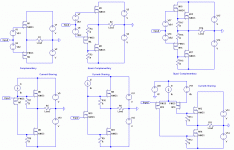
To continue the topic I attach here a drawing of few different topologies. I've used MOSFETs throughout for simplicity . Top row - fully complementary output and a couple of quasi-complementary configurations. Bottom row - current sharing with P-ch splitter, N-ch splitter and differential P-ch pair as splitter. Last one is a well known option.
Alex
Alex
Attachments
Re: Re: Quasi or not Quasi - that is the question.
Now he is Quasi himself, then what would you do Alex......
quasi said:Umm....do I get to vote?
Cheers
Quasi
Now he is Quasi himself, then what would you do Alex......
Re: Re: Quasi or not Quasi - that is the question.
Quasi, I knew you would not miss this thread. Please feel free to vote if you think it is the right way to solve this .
Cheers
Alex
quasi said:Umm....do I get to vote?
Cheers
Quasi
Quasi, I knew you would not miss this thread. Please feel free to vote if you think it is the right way to solve this
.Cheers
Alex
Can I vote for complementary?... Allthough I've allways had a soft spot for the quasi topologies nobody would even consider it if there would be a real perfect matched complementary transistors availeble.. or am I mistaken?
grzz, Thijs
ps let's stick to the original thread topic..
grzz, Thijs
ps let's stick to the original thread topic..
tschrama said:Can I vote for complementary?... Allthough I've allways had a soft spot for the quasi topologies nobody would even consider it if there would be a real perfect matched complementary transistors availeble.. or am I mistaken?
grzz, Thijs
ps let's stick to the original thread topic..
Hi Thijs,
yes, I suppose it is true. However the main question was - what to call "quasi" . In my view you can only use this word when you try to imitate a fully complementary topology with non-complementary devices. Otherwise we would call all valve amps and N-channel only amps with a transformer coupling also "quasi". Somewhere we should draw the line
. And it is true that there is no perfect complementary transistors in existance, especially bad the situation with MOSFETs as physics prohibits it. In any case two different structures would behave differently with current, temperature, transient power etc. even if they matched well in a particular point of characteristics. If you use two same devices and drive these symmetrically you can have symmetrical dynamic behavior and I consider that important in audio.
Cheers
Alex
oops sorry,
Offcourse ...I agree... it comes down to how the output stage is driven... if the previous stage is such that it could drive a complementary output stage.. then the output stage is quasi-complementary...
in other words.. it the output stage can be sustituted by a complementairy output-pair.. without changes to the previous stage, the output stage can best be called quasi-complementary..
I like your output stage overview btw...
tschrama said:oops sorry,
Offcourse ...I agree... it comes down to how the output stage is driven... if the previous stage is such that it could drive a complementary output stage.. then the output stage is quasi-complementary...
in other words.. it the output stage can be sustituted by a complementairy output-pair.. without changes to the previous stage, the output stage can best be called quasi-complementary..
I can not agree with that definition
. Any VAS can be coupled somehow to any output stage. What about a valve transformer output again? It can be happily driven by a conventional VAS. "Quasi-complementary" means "imitation-complementary", isn't it? If we "imitate" one of the devices in a fully complementary topology than it is "quasi", otherwise it is not. Put it another way - in a "quasi-complementary" you always can without really changing the topology replace a part of the circuit with a complementary transistor to make it fully complementary. If you can not do it, than the circuit can not be called "quasi".
Cheers
Alex
More Quasi, please...
I would personally like to see the advancements of Mr. White’s & x-pro's indulgence on this work. I think if there is something good worth exploiting, they may find it.
I find it difficult to understand a persistent negative flow from critics and detractors but then again that is the true fuel to real discovery, even if it only results in a lesson learned.
Shawn.
- Status
- This old topic is closed. If you want to reopen this topic, contact a moderator using the "Report Post" button.
- Home
- Amplifiers
- Solid State
- Quasi or not Quasi - that is the question