The purpose of feedback is to inject a small portion of the output signal back into the amplifier for corrective behavior. The RC to gnd combined with the with the other RCs together form an impedance dividor network. Without the RC to gnd you would have 100% feedback which would effectively reduce your gain to 1.
The Cs (both of them) usually have 2 purposes. The first is to block DC so that you would have 100% feedback at DC which provides some minimal form of DC protection. The 2nd is to modify the feedback response at high frequencies which helps limit oscillations in your amplifier.
In order to analyze the behavior, you analyze the frequency response of the entire feedback network by determine the impedance of both Cs at various frequencies (or simply chart the equation w/rt to frequency) and use Ohms law to caculate the feedback.
--
Danny
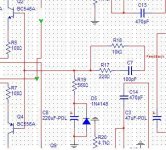
What is the purpose of R6(18k) and C2(2n2)? It is placed on base of inverting differential pair, but not part of voltage divider. R6 is quite big, 18k.
http://www.diyaudio.com/forums/attachment.php?s=&postid=491822&stamp=1097786469
http://www.diyaudio.com/forums/attachment.php?s=&postid=491822&stamp=1097786469
the RC network (R6, C2) is an attempt at reducing the possibility of oscillation, however, if it's a ;ow impedance at a frequency where the phase delay through the amplifier is 180 degrees, it will do the opposite, because the output of the differential pair will then be in phase with the oscillation. it's better to limit the frequency response of the VAS with a miller cap (b-c on Q11).
Hi, Unclejed,
It is not mine, I found the schematic here : http://www.diyaudio.com/forums/showthread.php?postid=491822#post491822
I'm still not clear about putting R+C in inverting input base of differential pair (that is not part of voltage divider) can prevent oscilation?
It is not mine, I found the schematic here : http://www.diyaudio.com/forums/showthread.php?postid=491822#post491822
I'm still not clear about putting R+C in inverting input base of differential pair (that is not part of voltage divider) can prevent oscilation?
it will prevent oscillation sometimes, because it causes a phase shift at the rollover frequency of the RC network, but let's say for sake of argument that the amp has a 180 degree phase shift of 180 degrees at for example 500khz (this happens in any amp due to junction capacitances of the transistors, and cannot be avoided), and the amp gain at that frequency is still above 1 (above unity gain). the reactance of the capacitor is much lower at high frequencies, and will pass more signal at 500khz back to the inverting input than at lower frequencies. since the phase shift of the rest of the amp at 500khz is 180 degrees, you are feeding back an inverted 500khz wave back to an inverting input, which is a "double negative". so instead of cancelling the oscillation, it's actually amplifying it. at all other frequencies, the cancellation effect of the inverting input works, but when the phase of the amp is 180 degrees it does the opposite. the attempt was made with this RC network to limit the high frequency response of the amplifier (probably to "stabilize" it)...... when i get time, i'll model this amp and see what happens. i suspect i'll find lots of even harmonic distortion (from the diodes in the output stage) and plenty of high frequency instability. i also don't know why the designer made such a weird DC servo...... it can be done with a single op amp..... looks like he was trying to correct another double negative there. a single op amp inverting integrator feeding through a high resistance into the noninverting input of the amp would have been sufficient....
- Status
- This old topic is closed. If you want to reopen this topic, contact a moderator using the "Report Post" button.
- Home
- Amplifiers
- Solid State
- Purpose for RC network on Feedback