Hi
I´ve been reading this forum for the last few months, and i fell ready to build something. I like to design my own schematics so i´m going to start with something simple.
I simulated the design and with works fine but i don´t no how it will work in real life. So any comments are welcome.
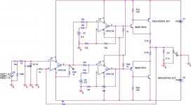
The first opamp does the voltage gain and and the feedback. Opamp 2 and 3 generates the bias to drive the mje15031/30. The output is biased to class A. The output power is around 16 W/8Ohm that i believe is more than enough.
Thanks
João
I´ve been reading this forum for the last few months, and i fell ready to build something. I like to design my own schematics so i´m going to start with something simple.
I simulated the design and with works fine but i don´t no how it will work in real life. So any comments are welcome.
The first opamp does the voltage gain and and the feedback. Opamp 2 and 3 generates the bias to drive the mje15031/30. The output is biased to class A. The output power is around 16 W/8Ohm that i believe is more than enough.
Thanks
João
Attachments
I believe it can be make simpler yet. Check out what Altec Lansing did in their 9446 power amp. EV made a nearly identical model the 3200. They both use a 5532 op amp to drive the output stage.
I guess I should mention that both amps haven't been made for a few years now. There are a lot still in service.
I guess I should mention that both amps haven't been made for a few years now. There are a lot still in service.
Hi,
the opa134 outputs have a resistor to Vrail to pull the output stage to single ended ClassA.
But, one is pulled to V+ and the other two are pulled to V- ,
will this work? Are the 134 output devices quasi or complementary?
Do V3 and V4 put a fixed 1.8V bias across the driver bases?
If so then the output stage is going to be seeing a lot of current. and the drivers only have ~6mA of collector current. where will the output device base current come from when Iout=>2Apk
darkfenriz said:The hard part is to make good, thermal tracking and adjustable voltage sources V3 and V4. Otherwise it won't work good.
Indeed. Also note that the two driver opamps have a gain of two so the bias is also amplified by two, giving more than 3 amps quiescent current. Isn't that a bit too high?
Jan Didden
About thermal track i´m thinking of doing it with the diodes in the output bjt's.
The quiscient current it's only 1.1 A at 15 V gives 16 W not much.
The U2 and U3 are adders with voltage gain = 1. So i´m only biasing the drivers with 0.9 V and 100 uA.
They only shif (+0.9 U2 and -0.9 U3) the signal from U1.
I think that pull up or pull down in the output of the opamp will both put it in class A.
Thanks for the comments.
I know that some say that opamp will degrade sound, but will these kind of opamp (0,00008 % THD) destroy much the quality of sound?
jnmar said:About thermal track i´m thinking of doing it with the diodes in the output bjt's.
The quiscient current it's only 1.1 A at 15 V gives 16 W not much.
[snip]
Sure? I see about 1.1V across the the 0.33 ohms Re's in your diagram and that's > 3 amps.
Edit: No, you're right! The bias is halved and then amplified x 2 still 0.9V gives about an amp. My bad!
Jan Didden
Depends on the load they are driving.jnmar said:...
I know that some say that opamp will degrade sound, but will these kind of opamp (0,00008 % THD) destroy much the quality of sound?
I believe AndrewT questions above are related to that.
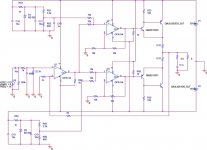
Made some changes remove V3 and V4, bias generator and replace them with a zener to give me around 5V. Then regulate the bias for each output via R52 and R56. Maybe a 7805 will give better results but i can´t find the spice model for it.
What kind of Thermal Tracking do you suggest?
Thanks for the help.
What kind of Thermal Tracking do you suggest?
Thanks for the help.
Attachments
from what i've read, resistors alone don't make very good current sources (re the opamp in class A). at the expense of some complexity, consider a JFET current source? maybe that would help matters.
neat page on biasing opamps into class A:
http://tangentsoft.net/audio/opamp-bias.html
neat page on biasing opamps into class A:
http://tangentsoft.net/audio/opamp-bias.html
janneman said:
Edit: No, you're right! The bias is halved and then amplified x 2 still 0.9V gives about an amp. My bad!
Jan Didden
But it's still 32W or so, not 15, idle dissipation for the whole output stage.
This approach reminds me of the Musical Fidelity A1 - there, bias tracking is automatic, by virtue of the driving amp (discrete) for bottom and top half keeping the LF filtered drop (approximating DC) on the emitter resistors of the output stage, constant.
In the A1, two discrete front ends, drive one half of the output stage eachh, one does the top half, one the bottom. An oposite offset voltage is introduced to the output of each of the halves, positive for top, negative for bottom. The top and bottom outputs are connected to each other via two 0.22 ohm resistors in series, with the output taken at the midpoint where the 0.22 ohm resistors join. Because the halves have a DC offset, it makes for a constant DC current flowing from one to the other, i.e. establishes bias current. The separate DC feedbacks of each half of the amplifier make certain that all thermal drift is compensated, and the bias current is constant. AC gain is handled similar to other amps, introducing a capacitor in series with resistor to ground from each amp half's inverting input.
This approach has the disadvantage that the output resistors are in effect in series with the 'virtual' amplifier output, appearing as roughly half of 0.22 ohms in series with the output impedance. With a slight re-arrangement of the feedback, it is possible to include the added output resistance inside the global feedback loop for AC, although it should be noted that the 'default' added resistance adds a measure of stability when driving reactive loads.
It is possible to construct a similar circuit with op-amp front ends instead of discrete - two op-amps would be needed.
Ops. I forget one cap... at the negative zener.
Also increase the value to 4.7u.
Also increase the value to 4.7u.
bikehorn said:from what i've read, resistors alone don't make very good current sources (re the opamp in class A). at the expense of some complexity, consider a JFET current source? maybe that would help matters.
i know that some kind of current mirror will do the job better but i want to keep it simple... (for now).
Attachments
Ops forget one cap... At the negative zener. Also increased the value to 4.7u.
bikehorn said:from what i've read, resistors alone don't make very good current sources (re the opamp in class A). at the expense of some complexity, consider a JFET current source? maybe that would help matters.
I know but i want to keep it simple for now...
Looking at the opa datasheet to select the load and source resistor.
Thinking in changing the gain... at g=10 the thd rises alot.
Attachments

bikehorn said:from what i've read, resistors alone don't make very good current sources (re the opamp in class A). at the expense of some complexity, consider a JFET current source? maybe that would help matters.
neat page on biasing opamps into class A:
http://tangentsoft.net/audio/opamp-bias.html
so called bias into class a of op-amp outputs
should be done in a correct way
op-amps generally are trimmed and biased in output stage
to minimize distortions and have best possible performance
just adding one resistor, and so Increase The AC loading of the op-amp
may often make distortion worse = no good
Like in a few cases is done by professional applications
using a constant current source (one single JFET will make a simple and good)
for example from output to negative supply
is very much to prefer
====================================
We can see this better technique, in the Linear Technology LT1115 datasheet:
An externally hosted image should be here but it was not working when we last tested it.
The JFET at output of LT1115 (a very lownoise high class OP)
should be set to 2mA current to negative, -15V supply.
This is, in my opinion, how it should be done ....
... if this is any good to do at all.
Now for other op-amps, like OPA2134 etc.
the ideal current to use will probably be different
and also of course depending on what the op-amp will be driving, The LOAD.
====================================
You could try this so called 'class a' tweak.
But if nothing is improved,
or even, because of increased DC-load of output, gets worse.
you just skip this complication of your circuit.
I am, myself, very suspicious to do this thing.
I would not do it, if I wasn't 100% sure it would considerably improve something.
By see some figure to prove this.
As I told, these great op-amps are from beginning designed
with output stages,
that are constructed for optimal operation.
Constructed By people that in most cases:
- has better knowledge than 99% of DIY 'experts' here
- has superior test gear instruments in very high tech factory of big company
- test instruments most of us will never in life get near
- companies like Linear Technology, Burr-Brown ....
- uses folks hand picked by company for their skills
- in this very special area of IC-design and op-amp creation
- they are true specialists in what they do
- and they get paid for doing the best they can

A very good example of such person is Walt Jung.
Datasheet LT1115 - Ultralow Noise, Low Distortion, Audio Op Amp
New Year 2007
lineup - does trust good IC designs ... but not 100% blindly
.
Hi
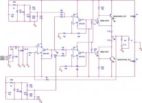
I added the Fet's and reduced the 'bias' current of the opamp's.
I don't really no if this improves the quality of the the output of the opamp. When i build it i will add a jumper to enable/disable the fet's.
I think this is done to keep the output transistor of the opamp always 'on'. Reducing any switch on/off distortion.
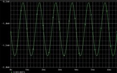
In the picture the output current of the opamp is always negative.
I know another question i have a Yamaha receiver RX-V457 it was a good sound. But i want something more. What project can i build that will give me more quality (not more power)?
My neighbors think that the power i have is more than enough...
I added the Fet's and reduced the 'bias' current of the opamp's.
I don't really no if this improves the quality of the the output of the opamp. When i build it i will add a jumper to enable/disable the fet's.
I think this is done to keep the output transistor of the opamp always 'on'. Reducing any switch on/off distortion.
In the picture the output current of the opamp is always negative.
I know another question i have a Yamaha receiver RX-V457 it was a good sound. But i want something more. What project can i build that will give me more quality (not more power)?
My neighbors think that the power i have is more than enough...
Attachments
AndrewT said:Hi Jn,
have you investigated if opa134 are quasi or complementary output?
Hi Andrew
Can't find that info. But why do you want to know that?
because you ignored my comment about pulling the opa134 output to V+ or V-.
If the output is quasi then only one way will work.
Even if it is complementary one often finds that performance favours pulling to one rail rather than the other (PNP are not usually as good as NPN on an IC).
If the output is quasi then only one way will work.
Even if it is complementary one often finds that performance favours pulling to one rail rather than the other (PNP are not usually as good as NPN on an IC).
AndrewT said:because you ignored my comment about pulling the opa134 output to V+ or V-.
If the output is quasi then only one way will work.
Even if it is complementary one often finds that performance favours pulling to one rail rather than the other (PNP are not usually as good as NPN on an IC).
The only data i found is from OPA637.
'The OPA627/637 is fabricated on a high-speed, dielectrically-
isolated complementary NPN/PNP'
So pulling it down will turn on (oh yes
) the NPN transistor.jnmar said:
The only data i found is from OPA637.
'The OPA627/637 is fabricated on a high-speed, dielectrically-
isolated complementary NPN/PNP'
So pulling it down will turn on (oh yes
If I was unsure, I would try to negative.
But, in my case as I told, I would probably only use whatever load I have
for 'pulling' the output stage symmetrically.
... that is, I wouldn't use any extra loading of output stage.
modern op-amps has no crossover distortion.
I think neither before or after applying the global feedback.
At least I have never seen any such distortion, anywhere I can remember.
- Status
- This old topic is closed. If you want to reopen this topic, contact a moderator using the "Report Post" button.
- Home
- Amplifiers
- Solid State
- Opamp Power Amp - Will it Work?