Has anybody experimented on different ways of bypassing the supplies of an opamp? I usually put a 10uF cap from each rail to ground and a .1 uF ceramic from the + supply to the - supply, and I try to keep all bypass caps as close as possible to the chip. Lately, I have been soldering the ceramic cap between the pins of the ic socket with excellent results. Are there any other arrangements with better performance?
Thanks!
-Chris
Thanks!
-Chris
You could also try to use MuRata-filter, ferrite bead, 10-100 ohms resistors. Those parts may isolate a bit from incoming noise. You can also have 100-470 µF together with 10-100 nF caps. SMD caps can also be very good but then a groundplane is a must.
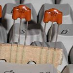
I use lot's of MuRata's in the industrial electronics, very good! The picture show a cap with the centre leg (one electrode) and the top connection (the other electrode) which is bent across the cap and two ferrite beads are inserted. This part requires groundplane in order to do the supposed job.
I recommend that you read the datasheets for the opamps in mind. Opamps faster than 10-20 v/µs needs normally special care .
Attachments
Soldering the cap between the pins is the best way to go for through-hole electronics. As you know, you get the capacitor as close to the pin leads as possible, and you keep the leads of the capacitor as short as possible. SMD devices are the best way to go here if you use a PWB.
I generally use a .01 uF high quality ceramic (Kemet CK05 types). Like Haldor says, for higher speed circuits, you may need to also parallel a smaller value capacitor. This is because the capacitor can turn inductive at higher frequencies - with lower value capacitors, in general, the higher this crossover frequency is. I also use tantalums of 6.8 to 10 uF, though not generally with each and every op amp package unless, possibly, the current draw is relatively high. I place these caps, ceramic and tantalum both, from +Vcc to ground and from -Vcc to ground.
Using series resistors of 10 to 100 Ohms can also be done if the current demand is relatively small. The resulting low pass filter will smooth out the current and reduce transients in the power supply wiring.
- Status
- This old topic is closed. If you want to reopen this topic, contact a moderator using the "Report Post" button.