I want to make a "good sounding" amp...if really exist such thing ...
and I want your advice in choosing the best possible schematics.
In this link--he use 4 pieces of MOS-FET 2SJ49/2SK 1344 parallel
Inverted Darlington connection NON-NFB stereo power amplifier,but for 150w:
http://www.ne.jp/asahi/evo/amp/J49K134/report.htm
I wonder if I use 2sk1058 and 2sj162 but only one pair-- is a good option ..I don't need too much power....
My concern is on "driver" match with the 2sk1058 and 2sj162.
Another option will be BUZ 900 and BUZ 905 but I want to hear your opinions.
Or should I choose this but also with mosfet's mentioned:
Attachments
I would no doubt use
only 2SK1058 / 2SJ162.
This lateral pair is good for a bit 'lower' power.
Say 2-3 ampere peak output current.
Upto 1 ampere output current, performance of 2SK1058
is having very good linearity.
And most 95% of any music will be below 1 ampere output into 6-8 Ohm.
And I would go for using them WITHOUT that foldback darlington drivers.
The reason is you see, I have seen VAS stages with as little as 10 mA currents
drive such Lateral MOSFET many times before.
In real good hifi amplifiers!
..... and this has been with ONLY one Potentiometer
.. to set and control Bias in Output 2SK1058 / 2SJ162 ....
This can be done, if you use BIG HEATSINKS to reduce temp variations in output pair.
Still I would myself use a VBE multiplier for this ( like in your schematic R15/R16 + Q9 ).
In every case - big or moderate heatsinks etc..
It is more in line with my a bit perfectionist audio nature.
Even if circuit is simple it does NOT mean it should't be PERFECT!
If you like you could increase current in Q5 Q6 VAS stage to 15 or 20 mA.
I don't know how good 2SC3423 / 2SA1360 are in taking power?
Personally I would look for some other pair than 2SC2240 / 2SA970
to work at 10 mA or more.
They are at their best at very low currents 0.5 - 1.0 mA.
Try find some BC337 / BC338 / BC237 / BC238 / BC639 / BC640 equals and replacements.
They are better for when we get closer to 500mW powers.
They are specially made TO92 for a bit higher currents.
-----------------
For 2SC3423 / 2SA1360 you can use TO126. ( BD139/140 or MJE340/350 )
Especially if you increase to 15-25 mA in that important stage.
( for use with only 2SK1058 / 2 SJ162 in output )
But using BC639/640 type replacements transistors might be better.
I wonder how about something like
Fairchild MPSA42 *MMBTA42 **PZTA42
Fairchild MPSA92 *MMBTA92 **PZTA92.
They are TO92 for a bit higher current (and voltages).
Like some TO126 transistors, these are originally intended for video = a bit more currents + voltages.
But I know some members here at forum like the VERY MUCH
for good Audio Amplifiers.
http://www.fairchildsemi.com/ds/MP/MPSA42.pdf
http://www.fairchildsemi.com/ds/MP/MPSA92.pdf
Regards & New Year
lineup
only 2SK1058 / 2SJ162.
This lateral pair is good for a bit 'lower' power.
Say 2-3 ampere peak output current.
Upto 1 ampere output current, performance of 2SK1058
is having very good linearity.
And most 95% of any music will be below 1 ampere output into 6-8 Ohm.
And I would go for using them WITHOUT that foldback darlington drivers.
The reason is you see, I have seen VAS stages with as little as 10 mA currents
drive such Lateral MOSFET many times before.
In real good hifi amplifiers!
..... and
this has been with ONLY one Potentiometer .. to set and control Bias in Output 2SK1058 / 2SJ162
....This can be done, if you use BIG HEATSINKS to reduce temp variations in output pair.
Still I would myself use a VBE multiplier for this ( like in your schematic R15/R16 + Q9 ).
In every case - big or moderate heatsinks etc..
It is more in line with my a bit perfectionist audio nature.
Even if circuit is simple it does NOT mean it should't be PERFECT!
If you like you could increase current in Q5 Q6 VAS stage to 15 or 20 mA.
I don't know how good 2SC3423 / 2SA1360 are in taking power?
Personally I would look for some other pair than 2SC2240 / 2SA970
to work at 10 mA or more.
They are at their best at very low currents 0.5 - 1.0 mA.
Try find some BC337 / BC338 / BC237 / BC238 / BC639 / BC640 equals and replacements.
They are better for when we get closer to 500mW powers.
They are specially made TO92 for a bit higher currents.
-----------------
For 2SC3423 / 2SA1360 you can use TO126. ( BD139/140 or MJE340/350 )
Especially if you increase to 15-25 mA in that important stage.
( for use with only 2SK1058 / 2 SJ162 in output )
But using BC639/640 type replacements transistors might be better.
I wonder how about something like
Fairchild MPSA42 *MMBTA42 **PZTA42
Fairchild MPSA92 *MMBTA92 **PZTA92.
They are TO92 for a bit higher current (and voltages).
Like some TO126 transistors, these are originally intended for video = a bit more currents + voltages.
But I know some members here at forum like the VERY MUCH
for good Audio Amplifiers.
http://www.fairchildsemi.com/ds/MP/MPSA42.pdf
http://www.fairchildsemi.com/ds/MP/MPSA92.pdf
MPSA42 - Spice Model
NPN (Is=34.9f Xti=3 Eg=1.11 Vaf=100 Bf=2.65K Ne=1.708 Ise=16.32p Ikf=23.79m Xtb=1.5 Br=9.769 Nc=2 Isc=0
Ikr=0 Rc=7 Cjc=14.23p Mjc=.5489 Vjc=.75 Fc=.5 Cje=49.62p Mje=.4136 Vje=.75 Tr=934.3p Tf=1.69n Itf=5
Vtf=20 Xtf=150 Rb=10)
MPSA92 - Spice Model
PNP (Is=218.9f Xti=3 Eg=1.11 Vaf=100 Bf=99 Ne=1.307 Ise=218.9f Ikf=.2016 Xtb=1.5 Br=24.67 Nc=2 Isc=0
Ikr=0 Rc=7 Cjc=19.88p Mjc=.4876 Vjc=.75 Fc=.5 Cje=81.49p Mje=.3493 Vje=.75 Tr=516.9p Tf=1.395n Itf=1.5
Vtf=22 Xtf=270 Rb=10)
Regards & New Year
lineup
@lineup
Hmmm..."you are bread and butter"....very simple and straight answers.
Thank you for that....but....
From these two schematics....what should I choose?...and maybe some words for BUZ "sound" quality ?...replacing 2sk and 2sj.
This one is NON-NFB.I think global nfb.Also..I'm thinking one pair of mosfets.
And...comparing that two schematics...topology...what do you think sounds more "perfect" for you....at list on paper.
I don't want to make a good sounding amp...I want to do an VERY high quality amp including all....from gain stages...to driver stages and finally power stage.
Any thoughts?
Attachments
Hi Felix,
I cannot assess your schematic for quality.
I can confirm that 3423 is an excellent choice for low current duty.
It suits pre-driver and VAS duty.
In my opinion it does not suit driver duty. At high frequency the FETs' capacitance are asking for too much current from the 3423/1360 pair.
I don't understand the purpose of D5 & D6? Can you explain?
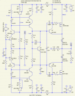
D5,D6 it seems to be for protection but from what I know this is not proper implementation.The sch. is not my design.More on this here:
http://www.diyaudio.com/forums/showthread.php?s=&threadid=77502&pagenumber=4
Also the measurements:
http://gaydenko.com/simple-ab/measure/
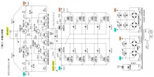
The japanese non feedback or global feedback topology:
http://www.ne.jp/asahi/evo/amp/J49K134/3.gif
http://www.ne.jp/asahi/evo/amp/J49K134/zu3.pdf
What do you think about this japan sch.?
http://www.diyaudio.com/forums/showthread.php?s=&threadid=77502&pagenumber=4
Also the measurements:
http://gaydenko.com/simple-ab/measure/
The japanese non feedback or global feedback topology:
http://www.ne.jp/asahi/evo/amp/J49K134/3.gif
http://www.ne.jp/asahi/evo/amp/J49K134/zu3.pdf
What do you think about this japan sch.?
Attachments
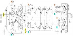
Another good reports ...very similar with "francaise Nelson Pass" Zenquito or Buzquito but this time with more "stable" and more efficient current stage:
http://www.ne.jp/asahi/evo/amp/J113K399/6.gif
http://www.ne.jp/asahi/evo/amp/J113K399/6.gif
Attachments
felixx said:@lineup
Hmmm..."you are bread and butter"....very simple and straight answers.
Thank you for that....but....
From these two schematics....what should I choose?
...and maybe some words for BUZ "sound" quality ?...replacing 2sk and 2sj.
This one is NON-NFB.I think global nfb.Also..I'm thinking one pair of mosfets.
------------------------------
Any thoughts?
thanks for details i did not have in mind when answering first
1. No global feedback
2. I get it it is not true class A? not 100 %.
250mA is what we can call high bias Class AB
- low levels in Class A
- but switch to Class AB for higher peaks
Most push-pull amplifiers are either
- Class AB, biased for only reduction of crossover dist
- Class A, to eliminate crossover dist
The normal bias for Lateral like 2SK1080 - 2SJ162 ia 80-100mA, for Class AB.
And no more.
There has been discussions here in this forum and at AudioAsylum forum about this.
Not once, but several times.
It is actually so, that this in between Hi bias Class AB
can be inferior in action,
compared to only take a Class B push-pull output stage
and bias for minimum crossover distortion.
And I am a believer in this!
Read for example Douglas Self investigation, stage for stage at his amplifier institute.
Written originally 1997 (and last update October 2001)
Distortion in Power Amplifiers
REFERENCES.
* 1] Lin, H C "Transistor Audio Amplifier" Electronics, Sept 1956, p173
* 2] Feucht "Handbook of Analog Circuit Design" Academic Press 1990, p256. (Pole-splitting)
* 3] Stocchino,G Letters, Electronics World, July 1995, p597.
* 4] Gray & Meyer "Analysis & Design of Analog Integrated Circuits." Wiley 1984, p194. (tanh law of simple pair)
* 5] Gray & Meyer Ibid, p256. (tanh law of current-mirror pair)
* 6] Gray & Meyer Ibid, p251 (VAS law is portion of exponential)
* 7] Self, D "Audio Power Amplifier Design Handbook." Newnes 1996, p231. ISBN 0-7506-2788-3 (poor FET linearity)
* 8] Self, D "FETs vs BJTs- the linearity competition." Electronics & Wireless World, May 1995 p387. (poor FET linearity)
* 9] Self, D "Distortion In Power Amplifiers, Part 8." Electronics & Wireless World, March 1994, p225 (Class A amp)
* 10] Self, D "Thermal dynamics of Power Amplifiers: I" Electronics World, May 1996, p410.
* 11] Self,D "Thermal dynamics of Power Amplifiers: II" Electronics World, June 1996, p481.
* 12] Self,D "Thermal dynamics of Power Amplifiers: II" Electronics World, Oct 1996, p754.
* 13] Self, D "Load Invariant Audio Power" Electronics World, Jan 1997, p16 (Beta droop)
* 14] Self, D "Distortion In Power Amplifiers: Part 5." Electronics World, Dec 1993, p1011. (HF switchoff distortion & losses)
* 15] Self, D "Audio Power Amplifier Design Handbook." Newnes 1996, p128. ISBN 0-7506-2788-3 (VAS linearisation reduces collector impedance)
* 16] Self, D "Distortion In Power Amplifiers: Part 3." Electronics World, Oct 1993, p820. (VAS linearisation)
* 17] Cherry, E "A New Distortion Mechanism In Class-B amplifiers." JAES May 1981, p237. (Inductive distortion)
* 18] Baxandall,P Private communication, 1995
* 19] Self, D "A Trimodal Power amplifier: I" Wireless World, June 1995, p462
* 20] Self, D "Load-Invariant Audio Power" Electronics & Wireless World, Jan 1997, p16
Douglas Self, London, Jan 1997.
About BUZ900 BUZ901 BUZ905 BUZ906
vs.
2SK-2SJ Lateral MOSFET from www.Renesas.com
I think the BUZ ones are the better ones.
The ones I would want and the ones I would use, if I had a real choice.
The only drawback and why I do not often mention them
is that they are difficult to fund and buy in most countries.
They were available some 5-10 years ago in my country.
At that time I did not really understand how good they were
even if I was very impressed by the construction and the data of these transistors.
At least compared to IRF HEXFET.
For example The Saint .. Anthony Holton of www.aussieamplifiers.com
http://www.diyaudio.com/forums/member.php?s=&action=getinfo&userid=2681
uses these in his high power and very high quality amps.
See my attachment of his NX-150 with BUZ901P / BUZ905P
See also a couple of other pictures and some posts of The Saint
in this topic, by suzyj:
My New Baby Amp
Here he is using one NX-150 with BUZ901P / BUZ906P.
I do not really know if it matters - but maybe sometimes BUZ905P is better complementary and sometimes BUZ906P.
") But the simple answer to this can also be, that you take what devices you have at home on your shelf for the moment ...
But the simple answer to this can also be, that you take what devices you have at home on your shelf for the moment ...Only Mister Holton knows the whole truth ....
Regards & Happy New Year 2007
lineup
Lineup Audio Amplifiers
http://lineup.awardspace.com/
Attachments
@lineup
Thx for info.
I read from the first time all links you send me and I talk "a little" with Mr.Anthony about implementation of Buz mos. Is not so difficult ...a few cautions.
My concern it was about topology of that two sch. and differences in sound between that two.
I know something about Suzy amp and also is hard to choose the right sch. for my needs.
Thx.
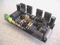
You should use shown mosfets, mount D5, D6 and Q9 on the same little Al-plate. D5, D6 are non-linear current sensors. As a result of such non-linearity, the amp has not cross-switching distortions while other class AB amps havefelixx said:Or should I choose this but also with mosfet's mentioned:
Also, the amp has very low memory distortions. As a result of all these, besides good measurements, the amp is very melodious Harmonics level lowering monotonically when
- input level lowers,
- harmonic number rises.
Such situation is typical for class A amps.
BTW, at final construction I have set ~180mA current for mosfets.
- Status
- This old topic is closed. If you want to reopen this topic, contact a moderator using the "Report Post" button.
- Home
- Amplifiers
- Solid State
- schematic to choose