OK, so I'm designing a microphone preamp. It is a transformerless, instrumentation type preamp with a fully balanced topology and quasi-floating output. It uses four op-amps.
Since I'm not using an input transformer, the circuit needs a good RF filter on the input. I've seen a few designs use RLC low pass filters. Without a filter the circuit is flat up to about 235 kHz at 66dB gain (simulated in Multisim).
How do I decide what frequency to set the filter at? I was thinking somewhere between 500kHz and 1MHz with a Butterworth response. Does this sound reasonable?
What is a good inductor to use? Would this be useable?: API Delevan shielded inductor
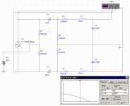
The attachment below shows the complete input section before the op-amps. This gave me an F3 of about 700kHz.
Since I'm not using an input transformer, the circuit needs a good RF filter on the input. I've seen a few designs use RLC low pass filters. Without a filter the circuit is flat up to about 235 kHz at 66dB gain (simulated in Multisim).
How do I decide what frequency to set the filter at? I was thinking somewhere between 500kHz and 1MHz with a Butterworth response. Does this sound reasonable?
What is a good inductor to use? Would this be useable?: API Delevan shielded inductor
The attachment below shows the complete input section before the op-amps. This gave me an F3 of about 700kHz.
Attachments
most microphones
even the finest professional!
has very limited freq response above 15-20 kHz
It is NOT like todays CD-DVD players and best digital audio.
Where they can have a FLAT response even above 100 kHz.
I guess you have a little lower price (than PRO) microphone.
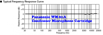
For example the Linkwitz recommended electret Panasonic WM-61A
has its decibel slope before 20 kHz.
In this way microphones are bit like loudspeakers.
The first bit in audio chain and the last
are in most DIY audio those with less wide upper AND lower bandwidth limits.
My own discrete transistor based electret microphone amplifer
(with unique circuit design! published elsewhere in this forum)
has got a upper roll off below 50.000 hertz.
And I am not worried!
The 1 kHz square waves response of this micamp is close to perfect!
No ringing or overshooting,
which is often a sign of TOO fast circuit, possibly with risk of oscillations
and other sort of problem / distortions.
If you put an input filter, RC, with -3dB around 100kHz,
you will have a mic amp with better quality,
than anybody with any AUDIO MIC alive would need.
Question is what instruments you have
that makes audible waves above 15.000 hertz.
And if you know some person that can hear such ultrasonic 'sounds'.
Batman can.
But I guess you are not HIM.
Or even close to alike him ....
Regards
lineup
Attachment:
Panasonic WM-61A frequency curve
Why does the curve end suddenly at about 17000 hertz ...
Yes, because they d not like to show it ... them Panasonic smart corporation dealers.
There are some things, we all have,
that we do not want all PEOPLE to see
and some things, we do not want ANYBODY to know about
even the finest professional!
has very limited freq response above 15-20 kHz
It is NOT like todays CD-DVD players and best digital audio.
Where they can have a FLAT response even above 100 kHz.
I guess you have a little lower price (than PRO) microphone.
For example the Linkwitz recommended electret Panasonic WM-61A
has its decibel slope before 20 kHz.
In this way microphones are bit like loudspeakers.
The first bit in audio chain and the last
are in most DIY audio those with less wide upper AND lower bandwidth limits.
My own discrete transistor based electret microphone amplifer
(with unique circuit design! published elsewhere in this forum)
has got a upper roll off below 50.000 hertz.
And I am not worried!
The 1 kHz square waves response of this micamp is close to perfect!
No ringing or overshooting,
which is often a sign of TOO fast circuit, possibly with risk of oscillations
and other sort of problem / distortions.
If you put an input filter, RC, with -3dB around 100kHz,
you will have a mic amp with better quality,
than anybody with any AUDIO MIC alive would need.
Question is what instruments you have
that makes audible waves above 15.000 hertz.
And if you know some person that can hear such ultrasonic 'sounds'.
Batman can.
But I guess you are not HIM.
Or even close to alike him ....
Regards
lineup
Attachment:
Panasonic WM-61A frequency curve
Why does the curve end suddenly at about 17000 hertz ...Yes, because they d not like to show it ... them Panasonic smart corporation dealers.
There are some things, we all have,
that we do not want all PEOPLE to see
and some things, we do not want ANYBODY to know about
Attachments
Actually this will be for professional use in my (modest) home studio. My most recent microphone purchase was a pair of Audio Technica AT4049a for $1000. An investment like that deserves to be connected to quality preamps. I decided I needed something better than the preamps in my Sony console. I know this won't be cheap, but I've never built anything to save money. It's all about the satisfaction of making my own equipment.
I know that mics, speakers and ears can't go that high, but a preamp should have a wide bandwidth even at high gain. There should be miniscule amplitude and phase shift over the audio spectrum. I wanted to try my hand at designing a preamp that would be on par with some of the best out there. For instance the Sytek MPX4Aii has very impressive specs and is similar to my design. The Sytek is a very pure and clean sounding preamp. I wanted to see if I could achieve similar results without the discreet front end.
I admit that 235 kHz is ridiculous; it's just what I achieved in simulation. I will probably limit it to 100 Khz with the feedback caps. I still need a good input filter because common mode rejection of the op-amps starts to drop above 1kHz.
Minion said:Take a Look at the Input of this design and see if the Input filter will be suitable for your design....
Cheers
Yes, that is similar to what I am considering. I had thought about using a common mode choke, but it seems that most are surface mount or the inductance is too high.
BTW did you design the preamp in your attachment?
MrTransistorm said:
BTW did you design the preamp in your attachment?
Hi, No I didn"t design that preamp, that was designed by "Samuel Groner" who has created Many Inovative preamp designs, I have a few simular preamp designs by him if you are interested....
I haven"t built any of these yet as they are a bit complex compared to many other simpler designs so it would a little to time consumeing for me to design a PCB for it Pluss I hate useing Rotary switches as Gain controlls.....
Cheers
MrTransistorm said:Actually this will be for professional use in my (modest) home studio. My most recent microphone purchase was a pair of Audio Technica AT4049a for $1000. An investment like that deserves to be connected to quality preamps.
------------------
I admit that 235 kHz is ridiculous; it's just what I achieved in simulation. I will probably limit it to 100 Khz with the feedback caps.
I still need a good input filter because common mode rejection of the op-amps starts to drop above 1kHz.
Mr Transistor Man.
You appears to have far better microphone than I thought, and than most of us have.
So, 235 kHz is not at all ridiculous.
If fact many VERY high quality preamps of all sorts
have had an upper roll off like 200-300 kHz.
Also I have found in my simulations, the optimal compromise for several different of my preamps
to be somewhere 100-600 kHz.
This is a compromise between stability and low distortion (nice square waves) on one hand
and on the other hand good speed, high slew rate and correct phase angles in audio band.
---------------------
Just a couple a weeks ago, I kept several hours to trimming a very good preamp with adding small caps.
When the virtual oscilloscope square wave was as good as I could get it,
( the best compromise for BOTH good 1kHz and 10 kHz Square at several levels and loads ),
I did run AC Analyse in this my EWB, Electronics WorkBench MultiSim9.
And the final resulting circuit was -3dB at 350 kHz.
The issue is, that when you have a real circuit in a PCB
there are other small capacitances added from real components tolerances, microphone cable, rails, leads etc.
These are impossible to predict and would be different for each built exemplar.
So there has to be another REAL TRIMMING done.
Hopefully those caps values from simulation will be a good starting point
for this final adjustments using REAL Oscilloscope.
-----------------------------
As I read from your posts, you know very well
what you are doing and what you are after.
So I think you will do just great to make a very good microphone amplifier system.
Please, later on, post some results and tell a bit how you did it.
I am sure it could be useful for someone thinking of his own similar project.
Thank you!
Regards
lineup
christmas - new year 2006-2007
- Status
- This old topic is closed. If you want to reopen this topic, contact a moderator using the "Report Post" button.
- Home
- Amplifiers
- Solid State
- input filter for microphone preamp