Hi guys,
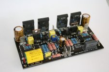
Here's a gratuitous pic of my new amp - a little 50W lateral MOSFET design destined for my study. It's essentially the same topology as my 100W one (in turn based on David Tilbrook's AEM6000), but I've taken advantage of the lower supply rails (+/-40V rather than +/-56V) and used MMBT06/56s in place of many of the MJE340s and 350s. It also only uses one pair of 2SK1058/2SJ162 lateral MOSFETs.
It simulates very well - 0.0005% THD at 1KHz (50W into 8 Ohms), and 0.004% THD at 10KHz (50W into 8 Ohms).
Cheers,
Suzy
Here's a gratuitous pic of my new amp - a little 50W lateral MOSFET design destined for my study. It's essentially the same topology as my 100W one (in turn based on David Tilbrook's AEM6000), but I've taken advantage of the lower supply rails (+/-40V rather than +/-56V) and used MMBT06/56s in place of many of the MJE340s and 350s. It also only uses one pair of 2SK1058/2SJ162 lateral MOSFETs.
An externally hosted image should be here but it was not working when we last tested it.
It simulates very well - 0.0005% THD at 1KHz (50W into 8 Ohms), and 0.004% THD at 10KHz (50W into 8 Ohms).
Cheers,
Suzy
fluckscapacitor said:can you post the schematic?
Ask and ye shall receive: http://www.littlefishbicycles.com/poweramp/50W_amp.pdf
Cheers,
Suzy
The Saint said:I love those low profile caps...
Here is my latest little amp what do you think?
I'm squeezing a pair of these, a 120W toroidal transformer, a preamp board, and a control board into a box 170 x 185 x 100mm. The 25mm high caps (highest that will fit) were really hard to get.
Your board looks really well laid out. You really need some SMD parts though
") You could start with the odd melf resistor. It's a slippery slope from there.
You could start with the odd melf resistor. It's a slippery slope from there.Cheers,
Suzy
" ... 0.0005% THD at 1KHz (50W into 8 Ohms), and 0.004% THD at 10KHz (50W into 8 Ohms) ..." ==== Aaaw 'some ...
...
Yes, what exactly is the total vertical height including any required stand offs or insulators?? (Will it fit inside a 1U rack mount chassis?)
A heat sink not required ?? (or is there some more parts we can't see yet?)
Kit soon? Modular amp soon?
" ... a preamp board, ..." ... ?? got a pic of that too?
FastEddy said:Yes, what exactly is the total vertical height including any required stand offs or insulators?? (Will it fit inside a 1U rack mount chassis?)
A heat sink not required ?? (or is there some more parts we can't see yet?)
Kit soon? Modular amp soon?
" ... a preamp board, ..." ... ?? got a pic of that too?
It's 33mm tall. 5mm for the MOSFETS (under the PCB), 3mm for the PCB, and 25mm for the filter caps. It'll fit easily into a 1U box.
The heatsink goes on the back. a pair of bolts go through the PCB, through the MOSFETs, and into the heatsink. It's a similar arrangement to what I did with my 100W amp.
Dunno about kits. It's too much of a derivative of Tilbrook's work for me to make money from.
The boards are designed but yet to be made for the preamp. It's a fairly simple affair with switching done using SSM2404 quad switches, an OPA2134 as a buffer, and a PGA2310 volume control.
felixx said:@suzyj
It seems you have a plate with an operational.
That don't "apear" on your schematics.
Could you tell us more about that?
I assume you're referring to the 8 pin SOIC? That's the SST404 matched dual JFET.
Cheers,
Suzy
suzyj said:Dunno about kits. It's too much of a derivative of Tilbrook's work for me to make money from.
Well, I could provide a SOTA design (less than 10ppm THD+N into 8R@20KHz ) from which you could make money, but it would cost you money!
Hi suzyj ,
I've found your shematic of this amp. I wanted to say that it looks alot like my designed amp last year. See the link.
I see that you've used two diff stages, problably to have some decent gain with the JFET's?
I've managed to find an other solution to have a relatif high gain? What do you think of this solution?
I have to admit that I still haven't found the time to build it yet.
http://www.diyaudio.com/forums/showthread.php?s=&threadid=70431
Greetz
Ben
" ... It's 33mm tall. ... It'll fit easily into a 1U box. ..."
" ... The heatsink goes on the back. a pair of bolts go through the PCB, through the MOSFETs, and into the heatsink. ... "
So by using a simple angle bracket of aluminum (or such) you could bolt to the bottom of a 1U rach mount case = using the mass of the case as the heat sink ...
" ... The heatsink goes on the back. a pair of bolts go through the PCB, through the MOSFETs, and into the heatsink. ... "
So by using a simple angle bracket of aluminum (or such) you could bolt to the bottom of a 1U rach mount case = using the mass of the case as the heat sink ...
suzyj and The Saint amplifier shown
hi
I have to say both these amplifiers shown
looks excellent work.
They are for us who love amps .. like Works Of Art!
suzyj
Image: http://www.littlefishbicycles.com/poweramp/50W_amp.jpg
The Saint
Image: http://www.diyaudio.com/forums/attachment.php?s=&postid=1087540&stamp=1166738073
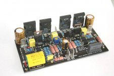
however they can be displayed a little bit better
This comes from the fact that when using digital camera indoors (not full daylight)
we usually have to adjust the brightness of pictures, a bit.
(Sometimes also adjust the R G B, red green blue, balance
to get closer to natural colors.)
I guess I am a bit of a perfectionist.
Because after loading my digital pictures to my PC
and before publish them here at diyAudio or in my websites,
I use my image editor program to ADJUST brightness, colors etc etc.
Take a picture of one of my circuits.
When editing image I take the actual circuit and put it beside my PC monitor,
while adjusting until image has got a suitable brighness + colors that looks as close the colors of my circuit and its parts.
After this I save the new edited copy, ready for upload / publishing.
=========================================
First:
I use a freeware image converter / editor with many many features:
www.XnView.com
It has many many nice features. This is only beginning of a long list.:
An example what can be done when you adjust and edit pictures.
The Saint, AussieAmplifiers.com
Attached image of amplifier:
http://www.diyaudio.com/forums/attachment.php?s=&postid=1087540&stamp=1166738073
If you compare this to My Attachment of Edited version of same Image
you will even be able to see, that IRF9610 and probably IRF610 is used
to drive the BIG MOSFET (absolute! top class BUZ901,BUZ906 Lateral MOS)
regards
lineup - website image editor specialist
hi
I have to say both these amplifiers shown
looks excellent work.
They are for us who love amps .. like Works Of Art!
suzyj
Image: http://www.littlefishbicycles.com/poweramp/50W_amp.jpg
The Saint
Image: http://www.diyaudio.com/forums/attachment.php?s=&postid=1087540&stamp=1166738073
however they can be displayed a little bit better
This comes from the fact that when using digital camera indoors (not full daylight)
we usually have to adjust the brightness of pictures, a bit.
(Sometimes also adjust the R G B, red green blue, balance
to get closer to natural colors.)
I guess I am a bit of a perfectionist.
Because after loading my digital pictures to my PC
and before publish them here at diyAudio or in my websites,
I use my image editor program to ADJUST brightness, colors etc etc.
Take a picture of one of my circuits.
When editing image I take the actual circuit and put it beside my PC monitor,
while adjusting until image has got a suitable brighness + colors that looks as close the colors of my circuit and its parts.
After this I save the new edited copy, ready for upload / publishing.
=========================================
First:
I use a freeware image converter / editor with many many features:
www.XnView.com
It has many many nice features. This is only beginning of a long list.:
http://perso.orange.fr/pierre.g/xnview/enfeatures.htmlImport about 400 graphic file formats
Export about 50 graphic file formats
Multipage TIFF, Animated GIF, Animated ICO support
Image IPTC, EXIF metadata support
EXIF auto rotation support
IPTC editing
...
An example what can be done when you adjust and edit pictures.
The Saint, AussieAmplifiers.com
Attached image of amplifier:
http://www.diyaudio.com/forums/attachment.php?s=&postid=1087540&stamp=1166738073
If you compare this to My Attachment of Edited version of same Image
you will even be able to see, that IRF9610 and probably IRF610 is used
to drive the BIG MOSFET (absolute! top class BUZ901,BUZ906 Lateral MOS)
regards
lineup - website image editor specialist
Attachments

Hi Lineup
Thanks for the tip with the photo enhancement.
[I'm squeezing a pair of these, a 120W toroidal transformer, a preamp board, and a control board into a box 170 x 185 x 100mm. The 25mm high caps (highest that will fit) were really hard to get.
Your board looks really well laid out. You really need some SMD parts though You could start with the odd melf resistor. It's a slippery slope from there.]
Yes SMD is the next step with these amps, I physically cannot go any smaller without SMD technology.
100 Watts Mosfet Power Amplifier
Dear Suzyj,
I write you because I am no more able to enter in your site www.littlefishbicycles.com, it seems that your contents are no more present there. Because of the fact that I would be interested in your project, would you like to tell me how to have all the files related to this project, and also regarding the preamp ?
If you have another site tell me because I will download the files from there.
Ciao from Italy
arm
javascript:smilie('')
Dear Suzyj,
I write you because I am no more able to enter in your site www.littlefishbicycles.com, it seems that your contents are no more present there. Because of the fact that I would be interested in your project, would you like to tell me how to have all the files related to this project, and also regarding the preamp ?
If you have another site tell me because I will download the files from there.
Ciao from Italy
arm
javascript:smilie('
')Attachments
I allowed my website to lapse, because I haven't been interested in it for a couple of years, and became tired of the inane questions that it kept generating.
Should you really be interested in the design, it's been archived by the www.archive.org - see http://web.archive.org/web/20071002223743/http://www.littlefishbicycles.com/poweramp/
A caveat though. The SST404 dual SO8 jfet that I used as an input differential pair is no longer readily available, as Siliconix dropped their jfet line. It's still being made by calogic, but I am unaware of anyone that stocks small quantities.
- Status
- This old topic is closed. If you want to reopen this topic, contact a moderator using the "Report Post" button.
- Home
- Amplifiers
- Solid State
- My new baby amp