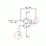
The source resistance resembles... well, the source resistance. It is the resistance measured between output and common (ground) of the (gain) stage feeding the tonestack. In electronic circuits that include capacitors or inductors the resistance (R) is different for different frequencies, this is a concept known as impedance (Z).
You can tweak the source resistance in TSC and find out that if it is considerably higher than the loading impedance (impedances of both tonestack and input impedance of the following stage) the signal will be attenuated more - especially at higher frequencies.
The circuit's modeled in TSC are not for tube amps only, I've seen those used in gazillions of guitar amplifiers - both solid state and tube. What is different between most solid state and tube designs are the source and load impedances. You need to find them out to tweak the tonestack to give you the needed frequency response with least amount of "insertion losses" (loss of gain due to passive circuitry).
I don't understand what you mean by asking what would be a good setting for 1Vpeak... All basic passive circuits work identically regardless of the signal amplitude. You obviously want the overrall signal attenuation to be lowest as possible, otherwise you will need massive amounts of gain to compensate all the insertion losses and the signal to noise ratio of your circuit will be very poor. Did this answer your question?
prorms,
You can't really measure your source resistance in that way. Trust me... just throw a zero in there and you'll be fine.
We can talk about how to measure the source resistance correctly. It will be very difficult to measure properly though... and will come out very close to zero anyway (really).

You can't really measure your source resistance in that way. Trust me... just throw a zero in there and you'll be fine.
We can talk about how to measure the source resistance correctly. It will be very difficult to measure properly though... and will come out very close to zero anyway (really).
....
the results form the tsc calculator are not the same results the
as the bread board when you convert the db to volts
example
with input at 1volt
for the eseries same circuit as when you frist in style
breadboard stats
with the pot turn on boost
185mv 1k = -14.7
365mv 100hz = -8.8
with the pot turn on cut
30mv 100hz = -30.5
21.3mv 1khz =-33.4
their not the same close but once start change parts around in the tsc the get alot different then the real circuit
so that why i ask about the resistor signal generator what would be the correct setting


- Status
- This old topic is closed. If you want to reopen this topic, contact a moderator using the "Report Post" button.
- Home
- Amplifiers
- Solid State
- Tone Stack Calculator or tsc ???????
