ghaudio,
you are right, but did I say differently?
The back EMF counteracts the driving current according to Lenz`s beautiful law of energy conservation, in order to maintain equilibrium between input and output power (otherwise things would explode into our faces). It is not about electrical damping.
Feedback lowers amplifier intrinsic resistance so high resistance is achievable with no feedback. Constant current drive means considerably enhanced speaker and amplifier linearity compared to constant voltage drive. The common source amplifier is a good choice.
Lenz's law says that the back emf tries to oppose the signal. If that signal is coming from a current source (i.e. infinite impedance) then the back emf has no effect. There is no electrical damping.
Feedback only lowers amplifier output resistance if it is voltage feedback. In this case the amp is no longer a current source.
I am sorry to say I am getting bored with this conversation. I keep correcting errors and WuYit keeps repeating them.
I will say it once more then shut up: a current source amp is a bad idea unless you have specially designed speakers. Such speakers will behave badly with a conventional voltage source amp. There are good reasons why the normal convention is voltage source amps.
"Tries" is an unfortunate word to be used here. Lenz's law says that the magnetic field induced by the current opposes the original cause of the induced current. Faraday could not solve this.Lenz's law says that the back emf tries to oppose the signal.
Since ideal values are not achievable, it is more appropriate to say "high impedance". A higher impedance means lower damping because of the relationship Blv / Z as stated in post #55.If that signal is coming from a current source (i.e. infinite impedance) then has no effect. There is no electrical damping.
OK.Feedback only lowers amplifier output resistance if it is voltage feedback.
More specifically, what errors?I am sorry to say I am getting bored with this conversation. I keep correcting errors and WuYit keeps repeating them.
Normal convention based on misconception, a widespread phenomenon in audio.There are good reasons why the normal convention is voltage source amps.
Not being part of the formula, voltage is a nuisance, causing disturbance. (Voltage signals will be converted to current signals under highly unfavorable circumstances).
F = Bli
where
Bl = motor strength
i = driving current
Not necessarily, but certainly, frequency response depends on impedance, the overall distortion reduction can easily outweigh a less flat frequency response.I will say it once more then shut up: a current source amp is a bad idea unless you have specially designed speakers. Such speakers will behave badly with a conventional voltage source amp.
I believe losing control of HF current when one hurls a pair of high local impedance
drains or collectors at each other, and keep watch only over the collision voltage...
We turn a blind eye to this trainwreck of obscene currents, and wish for the best?
My solution is a secondary feedback loop in quadrature. Fast enough to keep up with
music in real time. Watching output device currents, and regulating instantaneous
bias in the common mode. Kinda like what a "bias spreader" does, only faster. No cap.
Realtime bias spreading based on realtime output stage currents.
This second feedback acts at 90 degree angle to the main loop. Strange interactions
between 90deg cooperative loops practically nonexistent. Makes the main loop's job
easier and more linear. Harmonic requirements of the output stage drive are mostly
dealt with by the current loop (common mode drive), the voltage loop (differential
mode drive) doesn't have to bother with them.
This can be simple as 4 components. Ask me to prove it...
Last edited:
HI
Please answer lumanauw's question! Traditionally it is more difficult to stabilise a CFP, and the differences are interesting.
In the CFP when the output stage turns on - say for a 20 kHz signal - the drivers suffer a huge peak as the output transistors turn on (this is to overcome the inherent delay). They seem to be able to handle this peak better in the CFP than in the standard emitter follower. Crossover distortion, as a result, can be lower. Bias current stability is fantastic as the drivers are thermally connected to the bias stabiliser, the outputs are usually not tracked.
Except that when an output transistor turns off, the driver is still conducting, because of the emitter-base bias resistors (typically 47-100 ohms). In the full complementary output stage the base bias current is not connected to the load because a single resistor is connected between the output transistor bases. So this trumps on crossover distortion by avoiding - or trying to avoid - a dynamic change in open loop gain between driver transistors turning on and off -the drivers should stay in class A.
Also, the fully complementary Darlington output output stage is more stable as there is no internal loop as such.
SO it's a question of which provides the lowest apparent (i.e. audible) distortion. If the open loop gain is very high I doubt that the gain reduction of a driver transistor turning off would be detectable. On the conventional classic circuits with input transistor (or pair) and single VAS driver the OLG may not be enough to reduce this distortion. IF we take the output transistors to have a gain of 100, then for this to become less than say 0.1% change in OLG means having an OLG of at least 100,000...
John.
Last edited:
Again the assumption that outputs of class AB CFP must suffer a turn-off.
Only if minimum output current is less than base to emitter bypass current.
However, it is easy to have a diode protected reserve current completely
bypass the load and anything weird it might reflect. If this parasitic reserve
current is made slightly larger than driver current, neither output transistor
will ever have to suffer the issues of complete shutoff.
We are talking Class AB where B squashes flat against some minimum figure
higher than 0. Oh say: 100-200mA or thereabouts.
Last edited:
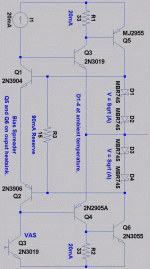
This can be even simpler in JLH-SRPP form, but you asked CFP's...
90mA at R3 sets an AB current minimum well above the drivers.
No more output shut-offs. OK, Schottky diodes will shut off, but
never transistors.
There is purposely no cap across the ACTIVE bias spreader.
Its managing bias in real time at 90 degrees to the main loop.
The problems of collector current blindness are avoided.
It also forces the output devices to perfect compliments,
at least as good as any two Schottkys might match...
Attachments
Last edited:
- Status
- This old topic is closed. If you want to reopen this topic, contact a moderator using the "Report Post" button.
- Home
- Amplifiers
- Solid State
- Why collector/drain output stages are so rare???