G.Kleinschmidt said:
It's really not that bad. A double sided SMD board with SOT-23 and SOT-223 transistors (the bottom layer power rail and grounding plane, top layer signal plane) really is a piece of cake to layout. I wouldn’t contemplate homebrewing this design with through-hole components though – too many holes to drill!
") I am sure you will make it.
I am sure you will make it.With some will power and work, we will do more than anyone think.
G.Kleinschmidt said:Preliminary schematic MKIII…….revised my offset voltage nulling scheme. Put a 100 ohm trimpot into the drain load circuit of each differential input amp……much nicer.....
May I have a bigger (readable) version? What sort of open-loop gain and gain-bandwidth product are you getting from it? I'd love to hear about your compensation scheme - with all those stages, I imagine it'll be a real challenge to compensate.
Looks pretty cool. I agree about layout - It wouldn't be too hard, though a double sided board is pretty-much dictated.
Cheers,
Suzy
suzyj said:
May I have a bigger (readable) version? What sort of open-loop gain and gain-bandwidth product are you getting from it? I'd love to hear about your compensation scheme - with all those stages, I imagine it'll be a real challenge to compensate.
Looks pretty cool. I agree about layout - It wouldn't be too hard, though a double sided board is pretty-much dictated.
Cheers,
Suzy
G’day Suzy.
I can email you the Protel (99SE) *.Sch file tonight it you want it.
Frequency compensation really isn’t an issue. The first opamp circuit is just a unity gain voltage follower with a cascoded jfet differential amplifier followed by a differential VAS with current mirror loading. The output stage is a class A complementary emitter follower.
The following fully differential opamp may have many stages, but they are not series connected; they’re just there to provide complementary outputs. The circuit is, admittedly, complicated a bit further with a secondary jfet differential amplifier to increase the open loop gain, but both differential stages have high bandwidth.
Also, many of the transistors in that circuit are part of the many constant current sources and biasing circuitry.
Cheers,
Glen
G.Kleinschmidt said:I can email you the Protel (99SE) *.Sch file tonight it you want it.
Hi Glen,
That would be really cool. My email address is suzyj AT littlefishbicycles.com.
Cheers,
Suzy
Lineup Original Design - Discrete Op Amp - 2N5551 2N5401
.
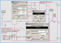
My most promising discrete opamp circuit, so far.
See attachment for circuit simulation test result.
Those 100 Volt JFET used can be ordered here: http://www.ampslab.com/components_fets.htm
Some additional facts of my discrete OP Amp.
Max 100 Volt DC single supply.
Max +/-50 Volt DC dual supply.
lineup
http://lineup.awardspace.com/
.
My most promising discrete opamp circuit, so far.
See attachment for circuit simulation test result.
Those 100 Volt JFET used can be ordered here: http://www.ampslab.com/components_fets.htm
.
2SK373-GR, Toshiba JFET, for Audio Amplifier; High Voltage; Constant Current
100volt, 2.6-6.5mA, 0.4watt, TO-92
Price at www.AmpsLab.com
2SK373-GR Toshiba High Voltage N-Ch JFET
US$30.00 for 20 pieces
.
Some additional facts of my discrete OP Amp.
Max 100 Volt DC single supply.
Max +/-50 Volt DC dual supply.
*
Lineup Original Topology:
1. Dual JFET input. JFET current source.
2. Complementary 2N5551, 2N5401 stage. To integrate gain from input stage.
3. Output Diamond Follower Buffer using 2N5551 and 2N5401. Biased with current sources.
Global Negative Feedback from Output to Input JFET stage.
Transistors used (not including current sources):
2 x 2SK373 (n-fet) 100 Volt DS
3 x 2N5551 (npn) 160 Volt CE
4 x 2N5401 (pnp) 150 Volt CE
Gives:
09 active Transistors
12 other Transistors used for current sources etc.
Total number = 21 transistors.
Power Supply:
+40 and -40 Volt DC
Total Supply Current, Idle: 11.3 mA
DC Input. Upper Frequency -3.0 dB roll off at 350 kHz
Bandwidth: DC - 350.000 hertz
20 Volt RMS, Test1:
Unity Gain ( x0.98; -0.18dB )
1.000 hertz, 1 kHz sinus
28.9 Volt peak input into 47 kohm
28.3 Volt peak output into 2 kohm = 20 Volt RMS
Result:
Distortion THD 0.000%
2nd harm: -107 dB
3rd harm: -115 dB
4th harm: -137 dB
Other harmonics are all below -130 dB
*
lineup
http://lineup.awardspace.com/
Attachments
suzyj said:
Hi Glen,
That would be really cool. My email address is suzyj AT littlefishbicycles.com.
Cheers,
Suzy
Hey! Did ya get the schematic, or wot?
G.Kleinschmidt said:
Hey! Did ya get the schematic, or wot?
G.Kleinschmidt
Why don't you make a bigger image?
And attach it here.
Some makes a ZIPPED file of their Image or PDF
and people can download ZIP
(this works, because images CAN NOT be bigger than 100kB)
It was same in start of topic:
you made very small image and after I asked you
you posted a bigger version.
Why can't you post a bigger version now:
As ZIP, or as some compressed image format.
===================
Well, you do what you want.
I have seen topics, where One Whole Forum page
is just a long row of posts from people asking to get something per EMAIL.
--- I find it a waste of forum space.
Who wants to read a topic, where what you see posted is
post after post with some Email Addresses begging for some file
Regards
lineup - only trying to advice & help with the practical side of this
suzyj said:Nope, and I just realised why, too. I gave you the wrong email address. Should have been suzy at littlefishbicycles.com (no j).
Cheers,
Suzy
OkeDokey, schematic resent...........
lineup said:
G.Kleinschmidt
Why don't you make a bigger image?
And attach it here
Hey, I will, eventually. It's just a really tedious process. In fact, I have been documenting a whole heap of projects for quite a while already, that I plan to publish on dedicated personal EE website. My complete amp project is on the list.
Problem is that there's only 24 hours in a day...........
Cheers,
Glen
The other option is of course, like several do,
use a 3rd website for uploading your BIG Images (>= 100kB)
.. or get yourself a free website for Storing your images.
This this way you can give the link to image
and people can
1) download your files, images
2) click on link to see your image
3) you can use the image tag to put such remote image, in your post
This is for example power amplifier of suzyj
An externally hosted image should be here but it was not working when we last tested it.
using this remote link (at suzyj personal homepage):
http://www.littlefishbicycles.com/poweramp/simplified_schematic.gif
you can also download this power amplifier schematic
in a bigger PDF file, with same schematic in full size
http://www.littlefishbicycles.com/poweramp/poweramp.pdf
Regards
lineup
------------------------------------------------------------------
This is an image I photographed with my Digital NIKON camera
at my website Lineup Audio Lab
one image of something you may have seen ...
http://lineup.awardspace.com/labtour-4.html
Another image from my website is attached here below.
I took it myself here at home - with my NIKON Digital.
Shows Power Supply for my own Class A Power Amplifier!!
Attachments
G.Kleinschmidt said:In fact, I have been documenting a whole heap of projects for quite a while already,
that I plan to publish on dedicated personal EE website.
My complete amp project is on the list.
...........
Cheers,
Glen
so is just a matter of timeGreat!
I can hardly wait to see resulting website.
Well to philosophical side of things .. those more essential stuffs
here is a new lineup quotation
made up in this minute:
our life ... is precisely and in fact this ... just a matter of timelineup said:
The other option is of course, like several do,
use a 3rd website for uploading your BIG Images (>= 100kB)
.. or get yourself a free website for Storing your images.
This this way you can give the link to image
and people can
1) download your files, images
2) click on link to see your image
3) you can use the image tag to put such remote image, in your post
Dude, I've done this already! Check this out:
http://homepages.picknowl.com.au/glenk/hybrid2.jpg
Unfortunately, I cant really entertain you much further with the stuff on my personal webspace, unless you like cars (another hobby besides DIY audio that keeps me broke)
.....My Rover:
http://homepages.picknowl.com.au/glenk/landrover/landrover.htm
My daily driver which currently does 13 sec 1/4 mile passes (but that will change when I rebuild the engine for 60% more power next year)......
http://homepages.picknowl.com.au/glenk/commodore/vk1.jpg
http://homepages.picknowl.com.au/glenk/commodore/vk2.jpg
http://homepages.picknowl.com.au/glenk/commodore/vk3.jpg
And my Zed. Was doing high 12 sec 1/4 mile passes, but I'm currently building a hotter motor for it....
http://homepages.picknowl.com.au/glenk/zed1.jpg
http://homepages.picknowl.com.au/glenk/zed2.jpg
Cheers!
Glen
Hi Glen,
Seeing as we should call you 'Mr. Excess' , I find it hard to believe that you gonna keep that 4 potter in that Landy! I would imagine you getting a 327 V8 in there, or something  Or do you plan an 'authentic' restoration? I would imagine it would be a PITA on long trips if you keep it standard (at least, they are terrible here in standard config )
Seeing as we should call you 'Mr. Excess'
, I find it hard to believe that you gonna keep that 4 potter in that Landy! I would imagine you getting a 327 V8 in there, or something Or do you plan an 'authentic' restoration? I would imagine it would be a PITA on long trips if you keep it standard (at least, they are terrible here in standard config )gbyleveldt said:Hi Glen,
Seeing as we should call you 'Mr. Excess'
LOL!
Yes, I'm doing an authentic resto on the Landy so I can put it on Historic Registration. These things have such a horrible ride, you really wouldn't want to push it beyond 80km/h on the highway anyway!
Cheers,
Glen
- Status
- This old topic is closed. If you want to reopen this topic, contact a moderator using the "Report Post" button.
- Home
- Amplifiers
- Solid State
- Super preamp.