Re: AD797 Clone people! Who can make a better one?
Hey aparatus...
On your schematic, what is the purpose of Q13?
cheers
Terry
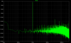
aparatusonitus said:I think I manage to bit you lineup...at least my sim tells me so

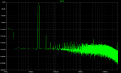
Below you'll find a circuit and FFt diagram at 1kHz and 20kHz (output at 1Vpp, load 600R)
Hey aparatus...
On your schematic, what is the purpose of Q13?
cheers
Terry
Re: AD797 Clone people! Who can make a better one?
Great! aparat//
.... god, what a difficult username you have chosen, to spell
I will have a look at you attachments.
At least is some sensible person,
that got some Inspiration here to try to make something Creative.
I have no doubts our circuits, even in real life, if built carefully
will outperform the non-existent posts with zero schematics,
from those 'better knowers'
... because i have not seen many amplifier from most of them.
From some not even an idea, to start working from.
But let them have it.
they are going nowhere, thinking they are already there
... while we are on our way, hoping to reach close to our goal:
Better Audio ideas and thinking in new banes ...
to find out something new and more.
There will always be 'nei-sayers'
because they can not come up with something of their own.
they see any progress from some other, in whatever direction
as a threat to their own lack of direction.
They are stuck ... not only in their spirit but in their mind process.
hope they have other things, where they can accomplish just a tiny thing,
because in Audio wont be anything we can see posted of value.
Good Luck with your work - your exploration - and your way.
Keep on, step by step ... the others are already way backwards bounds.
Regards to aparat
from
lineup
aparatusonitus said:I think I manage to bit you lineup
Below you'll find a circuit and FFt diagram at 1kHz and 20kHz (output at 1Vpp, load 600R)
Great! aparat//
.... god, what a difficult username you have chosen, to spell
I will have a look at you attachments.
At least is some sensible person,
that got some Inspiration here to try to make something Creative.
I have no doubts our circuits, even in real life, if built carefully
will outperform the non-existent posts with zero schematics,
from those 'better knowers'
... because i have not seen many amplifier from most of them.
From some not even an idea, to start working from.
But let them have it.
they are going nowhere, thinking they are already there
... while we are on our way, hoping to reach close to our goal:
Better Audio ideas and thinking in new banes ...
to find out something new and more.
There will always be 'nei-sayers'
because they can not come up with something of their own.
they see any progress from some other, in whatever direction
as a threat to their own lack of direction.
They are stuck ... not only in their spirit but in their mind process.
hope they have other things, where they can accomplish just a tiny thing,
because in Audio wont be anything we can see posted of value.
Good Luck with your work - your exploration - and your way.
Keep on, step by step ... the others are already way backwards bounds.
Regards to aparat
from
lineup
Re: Re: AD797 Clone people! Who can make a better one?
this is a very clever way to keep the voltage across Q12 CONSTANT
thayt is, it will be working in a narrow bit of the curves
in datasheet.
This means a more linear operation.
Because the gain of a transistor and other parameters
change with this vlotage, from C-E collector-emitter.
A bjt transistor has considerably less HFE at 1 Volt C-E than at 15 Volt.
But if voltage varies between 5-15 Volt,
the transfer curve is no longer close to a straight line, it has got a slope, a downhill.
It is a slightly bending curve. And this causes 'error' & 'local distortion'
that will put strain, extra work on feedback and cause more harmonics dist.
It is same reason, we see Cascoding in input / VAS stages
of normal type main stream Op-amp designed amplifiers.
One transistor to assist the one, that does the real work.
In this case, Q13 gives Q12 a constant environment to work in.
Regarding voltage.
there are imptortant factors we often use
to support constant parameters for transistors:
1. CCS, constant current
2. Constant voltage.
it is like if you would do a job, and you are dressed for summer
but while you are working, weather will change by the hour
between ice and snow and hot sun.
It will disturb your job
If is constant summer, you are dressed alright.
this Q13 Trick is new - it is not in the original AD797 circuit
and not in my schematics ....... yet !!!
lineup
Terry Demol said:
Hey aparatus...
On your schematic, what is the purpose of Q13?
cheers
Terry
this is a very clever way to keep the voltage across Q12 CONSTANT
thayt is, it will be working in a narrow bit of the curves
in datasheet.
This means a more linear operation.
Because the gain of a transistor and other parameters
change with this vlotage, from C-E collector-emitter.
A bjt transistor has considerably less HFE at 1 Volt C-E than at 15 Volt.
But if voltage varies between 5-15 Volt,
the transfer curve is no longer close to a straight line, it has got a slope, a downhill.
It is a slightly bending curve. And this causes 'error' & 'local distortion'
that will put strain, extra work on feedback and cause more harmonics dist.
It is same reason, we see Cascoding in input / VAS stages
of normal type main stream Op-amp designed amplifiers.
One transistor to assist the one, that does the real work.
In this case, Q13 gives Q12 a constant environment to work in.
Regarding voltage.
there are imptortant factors we often use
to support constant parameters for transistors:
1. CCS, constant current
2. Constant voltage.
it is like if you would do a job, and you are dressed for summer
but while you are working, weather will change by the hour
between ice and snow and hot sun.
It will disturb your job
If is constant summer, you are dressed alright.
this Q13 Trick is new - it is not in the original AD797 circuit
and not in my schematics ....... yet !!!
lineup
Re: Re: Re: AD797 Clone people! Who can make a better one?
Thanks Lineup,
Yes - I already understand all that stuff WRT constant voltage, cascodes, HFE etc etc etc.
But back to the central issue; I see Q9 and Q12 are basically a
darlington pair that drive the current mirror. So it's great to
linearise Q12 WRT constant voltage but what about Q9?
I'd do both or none.
When you think about it there are quite a few options WRT
driving the current mirror bootstrap. Probably the one which
offers best stability is more useful than any difference in the
region of -140dB THD.
Still - a nice effort.
Let's see some real world measurements into 600R at 10kHz and
say 5V rms.
cheers
Terry
lineup said:
this is a very clever way to keep the voltage across Q12 CONSTANT
thayt is, it will be working in a narrow bit of the curves
in datasheet.
This means a more linear operation.
Because the gain of a transistor and other parameters
change with this vlotage, from C-E collector-emitter.
A bjt transistor has considerably less HFE at 1 Volt C-E than at 15 Volt.
But if voltage varies between 5-15 Volt,
the transfer curve is no longer close to a straight line, it has got a slope, a downhill.
It is a slightly bending curve. And this causes 'error' & 'local distortion'
that will put strain, extra work on feedback and cause more harmonics dist.
It is same reason, we see Cascoding in input / VAS stages
of normal type main stream Op-amp designed amplifiers.
One transistor to assist the one, that does the real work.
In this case, Q13 gives Q12 a constant environment to work in.
Regarding voltage.
there are imptortant factors we often use
to support constant parameters for transistors:
1. CCS, constant current
2. Constant voltage.
it is like if you would do a job, and you are dressed for summer
but while you are working, weather will change by the hour
between ice and snow and hot sun.
It will disturb your job
If is constant summer, you are dressed alright.
this Q13 Trick is new - it is not in the original AD797 circuit
and not in my schematics ....... yet !!!
lineup
Thanks Lineup,
Yes - I already understand all that stuff WRT constant voltage, cascodes, HFE etc etc etc.
But back to the central issue; I see Q9 and Q12 are basically a
darlington pair that drive the current mirror. So it's great to
linearise Q12 WRT constant voltage but what about Q9?
I'd do both or none.
When you think about it there are quite a few options WRT
driving the current mirror bootstrap. Probably the one which
offers best stability is more useful than any difference in the
region of -140dB THD.
Still - a nice effort.
Let's see some real world measurements into 600R at 10kHz and
say 5V rms.
cheers
Terry
Re: Re: AD797 Clone people! Who can make a better one?
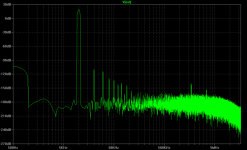
As a non EE, so please do correct me if I'm wrong, Q13 is there as a simple cascode to protect integrator formed by Q9/Q12 from PSU modulation. That way voltages at input, output, and common nodes of current mirror will better track voltage at amplifier output.
THD @ 10kHz at 600R load and 5Vrms
Terry Demol said:
Hey aparatus...
On your schematic, what is the purpose of Q13?
cheers
Terry
As a non EE, so please do correct me if I'm wrong, Q13 is there as a simple cascode to protect integrator formed by Q9/Q12 from PSU modulation. That way voltages at input, output, and common nodes of current mirror will better track voltage at amplifier output.
THD @ 10kHz at 600R load and 5Vrms
Attachments
Re: AD797 Clone people! Who can make a better one?
aparatu,
You may be right. you might have beat me.
But I sometimes say
( at least, it may upset some I know about in this board):
I say:
- Me lineup, is in some cases, steps ahead.
- When you are ahead, you are not understood
- Until the rest catches up with you
It may be when you say:
'earth revolves around sun- and not the opposite'.
.... or ....
When your ship sails in, and you tell people:
'there is a continent on the other side of Atlantic' ( Columbus 1492 )
Some board members live over there
and this is proof enough,
that Colombus was right
and the Nei -Sayers were deadly and Completely Wrong!
Tom Jones: It's not Unusual - you'll find it happens all the time....
........................................................................................................
About your circuit, aparatus:
----------------------------------------
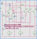
I did that darlington addition, in December 2006.
7 months before. 'Ahead' we may say
See my attached circuit - is one of my test versions from that period.
I did not bother to publish my later findings and improved figures.
Why Throw Pearls before The Svines.
But I am glad you are here now, finally!
A Pearl is a Pearl,
only to whom,
can see it is A Pearl
... those who can not see today, will maybe see tomorrow
... or in next Century .. of 2100-2199
Who lives will know & can tell
.. I will certainly not be around
more than as some dirty remains in a Grave, Somewhere.
With A Nice Engraved STONE standing above my head.
Regards
lineup
aparatusonitus said:I think I manage to bit you lineup
...at least my sim tells me so
.
aparatu,
You may be right. you might have beat me.
But I sometimes say
( at least, it may upset some I know about in this board
):I say:
- Me lineup, is in some cases, steps ahead.
- When you are ahead, you are not understood
- Until the rest catches up with you
It may be when you say:
'earth revolves around sun- and not the opposite'.
.... or ....
When your ship sails in, and you tell people:
'there is a continent on the other side of Atlantic' ( Columbus 1492 )
Some board members live over there
and this is proof enough,
that Colombus was right
and the Nei -Sayers were deadly and Completely Wrong!
Tom Jones: It's not Unusual - you'll find it happens all the time....
........................................................................................................
About your circuit, aparatus:
----------------------------------------
I did that darlington addition, in December 2006.
7 months before. 'Ahead' we may say
See my attached circuit - is one of my test versions from that period.
I did not bother to publish my later findings and improved figures.
Why Throw Pearls before The Svines.
But I am glad you are here now, finally!
A Pearl is a Pearl,
only to whom,
can see it is A Pearl
... those who can not see today, will maybe see tomorrow
... or in next Century .. of 2100-2199
Who lives will know & can tell
.. I will certainly not be around
more than as some dirty remains in a Grave, Somewhere.
With A Nice Engraved STONE standing above my head.
Regards
lineup
Attachments
Nordic said:Wow complex circuit... I guess you will need many matched pairs of transistors... will it be expensive to build considering this?
Not in my text book...in fact I see it as a very simple, elegant and extremely well behaved circuit... two tumbs up for Scott Wurcer.
If I could lend my hands to Philips BC846(B)S, BC857(B)S, BC850, 860 as well as BCP54/55/56 and BCP51/52/53 I'd start to buid it immediately. With these transistors, I think it will not be expensive to build at all, if you can deal with SMD parts.
who beat who
you had no good comment
to this
... and to my attached schematic
apparatus

.
well,
not easy maybe to answer,
when I did 8 months ago, what you just did now
... I wonder who is beating who
just asking
/lineup
##########################################
from
lineup
you had no good comment
to this
... and to my attached schematic
apparatus
.
well,
not easy maybe to answer,
when I did 8 months ago, what you just did now
... I wonder who is beating who
just asking
/lineup
##########################################
good day everbodyAbout your circuit, aparatus:
----------------------------------------
I did that darlington addition, in December 2006.
8 months before. 'Ahead' we may say
See my attached circuit - is one of my test versions from that period.
from
lineup
Re: who beat who
I've started to play with this toplogy in sim just a few days ago, so in that particular area no competition could ever exsist. Why don't you show as a real thing?
lineup said:you had no good comment
to this
... and to my attached schematic
apparatus
I've started to play with this toplogy in sim just a few days ago, so in that particular area no competition could ever exsist. Why don't you show as a real thing?
Re: Re: Re: Re: AD797 Clone people! Who can make a better one?
Good advice.
Or maybe try some other solution to bias those
########################################
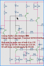
aparutus good attempt to make a smart bias, with high PSRR,
remains me of the following circuit Trick:
so
below you will see one of my Patents of Audio Ideas from last year.
for those who can read schematics
this will be 'self explainative'
Regards, lineup
Tim__x said:The Q20 Q19 current source biasing loop relies on leakage current to start, and as such it will likely fail to start with good small signal devices. Try adding a 1 meg resistor between the collectors of Q20 and Q19.
Good advice.
Or maybe try some other solution to bias those
########################################
aparutus good attempt to make a smart bias, with high PSRR,
remains me of the following circuit Trick:
so
below you will see one of my Patents of Audio Ideas from last year.
for those who can read schematics
this will be 'self explainative'
Regards, lineup
Attachments
Re: Re: who beat who
you are doing extremely well, aparatus!
What will become of you ....... !!!
I have posted many many pictures of my real things.
When I find it suitable, I will post some more.
People have very short memory, you see.
If you or anybody want to see pictures of my Audio Creations,
most of it direct-wired-solder Class A
I can recommend these topics ... they are full of it

we make ... Ugly But GOOOOOOD WORKING:
http://www.diyaudio.com/forums/showthread.php?postid=692464#post692464
and
http://www.diyaudio.com/forums/showthread.php?s=&threadid=96192
then you all can do the same, as Lineup did:
Post your Solid State pics!
Stuff you built, Ugly or not .....
Regards, lineup
aparatusonitus said:
I've started to play with this toplogy in sim just a few days ago, so in that particular area no competition could ever exsist. Why don't you show as a real thing?
you are doing extremely well, aparatus!
What will become of you ....... !!!
I have posted many many pictures of my real things.
When I find it suitable, I will post some more.
People have very short memory, you see.
If you or anybody want to see pictures of my Audio Creations,
most of it direct-wired-solder Class A
I can recommend these topics ... they are full of it
we make ... Ugly But GOOOOOOD WORKING:
http://www.diyaudio.com/forums/showthread.php?postid=692464#post692464
and
http://www.diyaudio.com/forums/showthread.php?s=&threadid=96192
then you all can do the same, as Lineup did:
Post your Solid State pics!
Stuff you built, Ugly or not .....
Regards, lineup
Nordic said:AD797 Clone people! Who can make a better one...
Better measuring or sounding?
What you prefer, Nordic
1. Make it measure mediocre, in order to get 'a good sound'
2. Make it measure very well, in order to have 'less enjoyable music'
some things make sense - others not
Regards, lineup
Re: Re: Re: Re: AD797 Clone people! Who can make a better one?
The difference, as I see it,
is the amount of current in Q9 vs. Q12.
Q9 has ~120uA, +/- a tiny
While the real variation of current into same point
comes from the driven transistor = Q12
But yes, ideally, them transistors, all 20, should
work at constant I + Constant V + Constant Temp + Constant Air Pressure (best is of course total Vacuum!)
... under all exsistent and possible operation conditions,
like input/output impedances/sources/loads/power supply variations
At such a working Point, in those Curves in Datasheets
! all parameters will be ABSOLUTELY without change = CONSTANT and Linear
.. well, 'linear' is probably an understatement here
... more like pointear
Regards lineup
Terry Demol said:
Thanks Lineup,
... back to the central issue;
I see Q9 and Q12 are basically a
darlington pair that drive the current mirror.
So it's great to
linearise Q12 WRT constant voltage
but what about Q9?
cheers, Terry
The difference, as I see it,
is the amount of current in Q9 vs. Q12.
Q9 has ~120uA, +/- a tiny
While the real variation of current into same point
comes from the driven transistor = Q12
But yes, ideally, them transistors, all 20, should
work at constant I + Constant V + Constant Temp + Constant Air Pressure (best is of course total Vacuum!)
... under all exsistent and possible operation conditions,
like input/output impedances/sources/loads/power supply variations
At such a working Point, in those Curves in Datasheets
! all parameters will be ABSOLUTELY without change = CONSTANT and Linear
.. well, 'linear' is probably an understatement here
... more like pointear
Regards lineup
Re: Re: Re: who beat who
Thx lineup, I do my best...
...And every amplifier needs good PSU like this (which is built and tested with original monolit AD797 opamp without any problem whatsoever regarding startup or oscilation). Note that these are a "integrated" W. Jung SupeRegulators with rectification and CRC filtering on board, so a current loop is extremely small. Thay look even better populated and in flash. And I buit these only to have a reference for my on going project of SuperShunt poz/neg regulators!
[/URL] [http://smg.photobucket.com/albums/v58/aparatusonitus/?action=view¤t=jung_reg007.jpg[/URL]
http://smg.photobucket.com/albums/v58/aparatusonitus/?action=view¤t=jung_reg013.jpg
lineup said:
you are doing extremely well, aparatus!
What will become of you ....... !!!
Post your Solid State pics!
Stuff you built, Ugly or not .....
Regards, lineup
Thx lineup, I do my best...
...And every amplifier needs good PSU like this (which is built and tested with original monolit AD797 opamp without any problem whatsoever regarding startup or oscilation). Note that these are a "integrated" W. Jung SupeRegulators with rectification and CRC filtering on board, so a current loop is extremely small. Thay look even better populated and in flash. And I buit these only to have a reference for my on going project of SuperShunt poz/neg regulators!
[/URL] [http://smg.photobucket.com/albums/v58/aparatusonitus/?action=view¤t=jung_reg007.jpg[/URL]
http://smg.photobucket.com/albums/v58/aparatusonitus/?action=view¤t=jung_reg013.jpg
- Home
- Amplifiers
- Solid State
- AD797 Clone people! Who can make a better one.