First words of all SWTP amplifier manuals -
"Mount all parts on circuit boards".
After building the 198 preamp and the 215 amp (25 watt channel stereo with dual diff front end and the "output triple") - those words still strike fear into my heart. My wife's too.
Over time, the amp turned out be pretty good. The preamp was another story. The only thing that would have helped the 198 would have been to burn it on altar with sheep guts.
CharleyW said:First words of all SWTP amplifier manuals -
"Mount all parts on circuit boards".
After building the 198 preamp and the 215 amp (25 watt channel stereo with dual diff front end and the "output triple") - those words still strike fear into my heart. My wife's too.
Over time, the amp turned out be pretty good. The preamp was another story. The only thing that would have helped the 198 would have been to burn it on altar with sheep guts.
Ah, the 215..I built 6 of those babies. Used them for the mids and highs at the club..
I never ever had a problem with them. They were so easy, I just used the heatsinks that I had left over from the tigers, and made a 2ru case for the 6 times 215, had the sinks on the back panel, allowed convection for cooling.
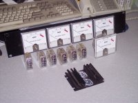
Just to provide a blast from the past, I remembered I had the VU meters from the tigers and the 215's in a cabinet...so here's a pic...the tigers are the biggies, the 215's had the edge meters.
Ooooh, where's my manners. The heatsink is from the tiger, it was one of 8 per amp (so I was up to my ears in them). Half were drilled mirror image, and were mounted inside the amp case (where their sole purpose in life was heat capacity.)
The tigers had a bulb with a green plastic cover to give green illumination, they charred within a month..
I don't know where the other 3 tiger meters are, but I'm sure they'll pop up someday..
Cheers, John.
btw...the meters were rather robust...I was able to use the slap of the meters on the right side of the unit to guage the loudness...biamping hides so much...
Attachments
Re: You are my Santa Claus Nordic... regards to Cape town and your family
Old, guys? Hmmmm, not that old!
Here's a Tigersaurus that I built from scratch: I was 16 when I did the mechanical layout, to fit the parts that I had purchased surplus. Didn't worry about how it looked or the size, that is a Hafler 500 on top of it. I upsized many of the resistors, and substituted higher power driver transistors. The series output stage design helped reduce the voltage across the output devices and stay in a better area of the SOA curve:
destroyer X said:This thread is my Christmas gift from you.
Thank you...lovely to remember those things.
I am sure many old guys are happy to watch... they do not come with the fear to be considered old...ahahahha..and they are!
regards,
Carlos
Old, guys? Hmmmm, not that old!
Here's a Tigersaurus that I built from scratch: I was 16 when I did the mechanical layout, to fit the parts that I had purchased surplus. Didn't worry about how it looked or the size, that is a Hafler 500 on top of it. I upsized many of the resistors, and substituted higher power driver transistors. The series output stage design helped reduce the voltage across the output devices and stay in a better area of the SOA curve:
An externally hosted image should be here but it was not working when we last tested it.
A friend gave me a Plastic Tiger amp with at least one channel blown. This reminds me of how, this particular amp made us think back in the day, that these designs were seriously lacking in design margin. One could even say that the design was completely flawed. The output devices are MJE3055/2955 which have a Vceo of 60V, yet the design runs on +/- 40V rails. This means that a full output signal with no load will certainly exceed the Vceo specification of the output devices. Also, they'll only handle 1A at 40V. These amps should be run at a maximum supply voltage of +/- 30V when using these cheap output devices. Really, for the small increase in price, there is no point in using these cheap devices. There are modern plastic devices with much better SOA and power handling.
Amp #1 in this pair has 2n5210s in the front end, SS1122/SS1123, and MJE3055/MJE2955 outputs.
Amp #2 has MPS6566s in the front end, MPSU06/MPSU56 drivers, and MJE2801/2901 outputs.
MPSU06/56 (MPSU07/57 are even better: Vceo=100V) look like good replacements for the SS parts, however they are discontinued and expensive on the surplus market.
Pete B.
Interesting stuff. I've only heard about the Tiger amps by their notorious reputation for blowing up. It's also quite difficult for a youngster like me (born 1980) to imagine a time when transistors were crap ")
I suppose the modern equivalent of the Plastic Tiger would be Rod Elliot's P3A design. Personally I am not a fan of CFP output stages, but even this design behaved itself when built (sensibly) on veroboard.
jackinnj, I know those lyrics quite well, but I didn't know the original author. To me, those lyrics come from a Tangerine Dream song.
The provided transformer for the Plastic Tiger was 42VCT at 2A, and gave about ±30V rectified and filtered. The 40V listed in the magazine article is a misprint.
The safe area of the MJ3055/2955 is 90W at 30V, or 3A. This would be a 90° load line, a pure capacitor. A real load would not be this bad. The pair of amplifiers would have 360W of safe area at room teperature, and the transformer was only 84VA. Not too shabby in my book.
"There are modern plastic devices with much better SOA and power handling."
But the key word here is 'modern', the 3055/2955 was a good choice 35 years ago.
edl said:
Nordic,
SS1122 = 2n5415, 2n5416
SS1123 = 2n3439, 2n3440
MPS6566 = bc182, bc546
SS1122 may be replaced by a BD 138 and SS 1123 by a BD 137, which avoid using of the small (imho, nasty) heathsink for old TO 5 case. In the schematic voltages are missed. My advice is to limit to a +/- 25 Volt maximum.
There is also a wasted opportunity in the schematic (of, pherhaps, a plain error in drawing... I don't know): connect R11 and R13 to the output devices PSU and connect the second PSU directly to the VAS and input section. This separe the amplifier in two distinct section as should be (imho).
Hi
Piercarlo
djk said:The provided transformer for the Plastic Tiger was 42VCT at 2A, and gave about ±30V rectified and filtered. The 40V listed in the magazine article is a misprint.
The safe area of the MJ3055/2955 is 90W at 30V, or 3A. This would be a 90° load line, a pure capacitor. A real load would not be this bad. The pair of amplifiers would have 360W of safe area at room teperature, and the transformer was only 84VA. Not too shabby in my book.
"There are modern plastic devices with much better SOA and power handling."
But the key word here is 'modern', the 3055/2955 was a good choice 35 years ago.
Thanks for the reminder, we did notice the transformer voltage after some consideration of the +/- 40 V misprint, still with resistors that smoke at full power I would say that these designs need more margin. +/-30 V is right at the limit of the output devices and does not offer margin for high line conditions or transient spikes.
You seem defensive of the Tiger Amps, they were certainly innovative and advanced for the time and an excellent value. However, they did often take out speakers when they smoked and failed which is certainly a major disadvantage. I prefer an even view of their strengths, and would like to see a fix to avoid failures and smoke.
The owner of this Plastic Tiger used his own power supply and I've not measured it yet. He said it took several tries replacing many parts to get it to work originally. It failed once during a lightening storm and took out a Warfdale speaker.
There are certainly many stories of Tiger Amps going up in smoke, enough to demonstrate IMO, that there was not enough margin in the design.
Pete B.
Here's what I would do:
1) Add emitter degen resistors to the LTP. 220R would be good enough, given the 2.0mA tail current.
2) Replace the 4.7V Zener with a couple of red LEDs, reduce R4 to 12K, and reduce R5 to 2.0K. LEDs are quieter (but they didn't exist in 1971).
3) Consider replacing the bias resistor and diode network with a Vbe multiplier.
4) Consider replacing the Sziklai pairs with full complementaries. Even though Sziklai's are supposed to have better sonics, they can be unstable. Not sure the difference is worth risking blowing something up.
"You seem defensive of the Tiger Amps"
Mine still work (with their original TO-127 3055/2955).
Tens of thousands of a similar amplifier were sold with the TO-220 version of this output that put out 50W into 4 ohms.
Even more of the bigger brother that would do 75W at 4 ohms from a single pair of TO-220 2N6488/91.
The basic design seems sound.
It was Walt Jung, after reviewing the Tigersaurus and analyzing it (in Audio Amatuer) who asked 'Dan Meyer, where are you?'. Dan Meyer was the designer. I think Walt Jung would have liked to have a little one to one with him about his amp on behalf of the many dissapointed . . . .
That output stage . . . scares the hell out of me, especially with the minimal compensation around the amp!
That output stage . . . scares the hell out of me, especially with the minimal compensation around the amp!
Tigers That Roared
I built a number of the UNIVERSAL TIGERS in the early '70s . I etched the boards and bought most of the parts from NEWARK ELECTRONICS. Danny Meyer brought me into the world of solid state audio and I was never disappointed . I lived in NYC at the time and could buy power transformers and big (5000uf) caps down on Canal Street for little money. As I recall the People at THE AUDIO AMATEUR ie Walt Jung and others didnt think much of the Meyer designs. They had a thing called The Williamson 20-20 with a quasi- complimentary output and a big cap in the output . I thought Danny's design was a much better idea. I often wondered what happened to Dan Meyer and THE SOUTHWEST TECHNICAL PRODUCTS CO. As I recall they did alot early computer stuff along with their audio efforts. I doubt that the stuff would stand up to todays designs but back then they were remarkable.
I built a number of the UNIVERSAL TIGERS in the early '70s . I etched the boards and bought most of the parts from NEWARK ELECTRONICS. Danny Meyer brought me into the world of solid state audio and I was never disappointed . I lived in NYC at the time and could buy power transformers and big (5000uf) caps down on Canal Street for little money. As I recall the People at THE AUDIO AMATEUR ie Walt Jung and others didnt think much of the Meyer designs. They had a thing called The Williamson 20-20 with a quasi- complimentary output and a big cap in the output . I thought Danny's design was a much better idea. I often wondered what happened to Dan Meyer and THE SOUTHWEST TECHNICAL PRODUCTS CO. As I recall they did alot early computer stuff along with their audio efforts. I doubt that the stuff would stand up to todays designs but back then they were remarkable.
Actually if the truth be known the "Tigersarous" has faired a heck of a lot better than the Ampzilla and SAE design of the wonderfull James B. I still have a working fully functional pair of the 250 watt mono block amplifiers sitting on my shelf ready to be auditioned again. They still have ALL the original outputs and I have never had a problem with them as long as I didn't use the input with the tantilum cap. The output stage is beefier than the SAE 2400 or Ampzilla by a long shot and it is a vastly better sounding amplifier.
I still have a friend with a pair or two of the "Tigers" and they are still working. A lot has to be said for this design as it was probably superior to a number of designs of the time. The man made the most out of what was available at the time.
I still have a friend with a pair or two of the "Tigers" and they are still working. A lot has to be said for this design as it was probably superior to a number of designs of the time. The man made the most out of what was available at the time.
burnedfingers said:Actually if the truth be known the "Tigersarous" has faired a heck of a lot better than the Ampzilla and SAE design of the wonderfull James B. I still have a working fully functional pair of the 250 watt mono block amplifiers sitting on my shelf ready to be auditioned again. They still have ALL the original outputs and I have never had a problem with them as long as I didn't use the input with the tantilum cap. The output stage is beefier than the SAE 2400 or Ampzilla by a long shot and it is a vastly better sounding amplifier.
I still have a friend with a pair or two of the "Tigers" and they are still working. A lot has to be said for this design as it was probably superior to a number of designs of the time. The man made the most out of what was available at the time.
Yes I agree that the "Tigersarous" was a much cleaner design than the Ampzilla which I also considered building.
My main complaint about the Universal and Plastic Tigers was that they were slightly underdesigned, when thermal derating is taken into consideration. Many if not most were shipped without output protection which was added later. There was a stereo version of the Universal Tiger that did not have enough heat sink IMO or any thermal switch shutoff.
Pete B.
djk said:"You seem defensive of the Tiger Amps"
Mine still work (with their original TO-127 3055/2955).
Tens of thousands of a similar amplifier were sold with the TO-220 version of this output that put out 50W into 4 ohms.
Even more of the bigger brother that would do 75W at 4 ohms from a single pair of TO-220 2N6488/91.
The basic design seems sound.
Hi djk,
I'd like to see the schematics for these similar amps that you mention if possible.
Pete B.
"I'd like to see the schematics for these similar amps that you mention if possible."
Rockford Fosgate.
I can barely read my copy of the PR-250 schematic. It is black with white traces, and over thirty years old. Does not scan well.
The PR-250 used a Royer type inverter with three pair of 3055.
The amplifier used 3055/2955 with the A05/55 as drivers, and a pair of 1N4003 for bias. The emiter resistors for the drivers are 36R, collector load are 68R, feedback are 43R with 2n7 in parallel. The 3055 had a 0R1 for current sensing and power supply protection. Front end was the NE5538.
Punch 150
(from memory, cannot find schematic)
Hexfet PWM inverter with three pair of IRFZ44.
The amplifier used 6488/91 with the A06/56 as drivers, and a pair of 1N4003 for bias. Front end was the NE5532. The feedback resistor around the output/driver pair was dropped, and only the cap was used (cannot remember the value of the cap).
Later versions went to using Hexfet outputs (circa 1987).
Plastic Tiger Schematic with Voltages
I just found this forum recently and it brought back many fond memories of building and hoping.
I built the Plastic Tiger from PE back in 1972. It took awhile to gather all the parts locally, however I had to get the SS1122, SS1123 from SWTPC. I built twin 30V+/- supplies as per the article design and housed the assembly in an old fridge tray made of aluminum with giant heatsinks screwed on the back for the outputs and biasing "diodes".
I was using a Dynaco PAT4/ST120 combo at the time with my AR 2ax speakers. After listening to both amps critically I unhooked the St 120 and never looked back.
This was my main sound system for about 15 years until it got replaced and retired to the shop where it has been running for the last 15 years continuously 24/7.
Amongst my collection is this schematic with the voltage test points that was published by SWTPC.
Thank you to the poster for the magazine scans as I failed to find my treasured dog-eared original copy.
By the way I "smoked the first set of SS's by hooking up the biasing diodes backwards. Imagine the teen angst at the wait for replacements from Texas to Vancouver.
I have loved the performance of this little bugger for these many years. The little plastic tiger gets to spend his "golden" years driving an old original pair of Dynaco A-10s spoonfed by the PAT-4
I just might try to build another one with the transistor substitutions. If anyone has suggested mods that I've missed maybe someone could reference this diagram for modification locations.
Thank you all for the contributions
G
ps: I hope the attachment worked
Attachments
- Status
- This old topic is closed. If you want to reopen this topic, contact a moderator using the "Report Post" button.
- Home
- Amplifiers
- Solid State
- 1971 Plastic Tiger