Ok I have an old marantz 510m that needs a new left driver board and possibly some new transistors. I'm going to try to bring this baby back to life. I am new to this and it is going to be a learning experience so please be patient.
Pics of the working board that I am going to replicate.
Front:
Back:
The Schematic:
...
Pics of the working board that I am going to replicate.
Front:
An externally hosted image should be here but it was not working when we last tested it.
Back:
An externally hosted image should be here but it was not working when we last tested it.
The Schematic:
An externally hosted image should be here but it was not working when we last tested it.
...
An externally hosted image should be here but it was not working when we last tested it.
sound_prodigy said:Ok I have an old marantz 510m that needs a new left driver board and possibly some new transistors. I'm going to try to bring this baby back to life.
Nice project. Resurrecting is good.
")
If only we could teach Google to solder...life would be different.
Best wishes,
Shawn.
Hi sound_prodigy,
That's a double sided board, isn't it? You still connect the dots but on both sides. You may need to solder small wires across to connect the bottom to the top pads in some cases. The original was plated through. That means desoldering may take longer.
Order 2X the capacitors you need and redo your other board while you are at it. You may need to use a TO-126 or similar case for the TO-5 transistors unless you can find those push on heatsinks.
Keep in mind that Marantz would match transistor compliments and pairs. Also, one stage was only one gain grouping away from the next stage. The manual would give you more detail (I don't have any more). I do have the schematic, as you do.
-Chris
anatech said:Order 2X the capacitors you need and redo your other board while you are at it. -Chris
Those boards are small and well laid out with lots of clearance. If you created two new boards, you go to heaven and why not? If you are generating a new PCB then making two is the same cost. Components for one board vs. doing two...same thing; almost the same cost. Do it all, do it the best you can.
So I guess I agree with Chris but on STEROIDS!
Cheers,
Shawn.
Ok, How do I tell the rating of the resistors.
They are all color coded. I understand that much, but do the bigger ones have different specs? Also some resistors are different colors.
This is a grey resistor, I can't tell if the tolerence is the green band or the red band.
Another one
They are all color coded. I understand that much, but do the bigger ones have different specs? Also some resistors are different colors.
This is a grey resistor, I can't tell if the tolerence is the green band or the red band.
An externally hosted image should be here but it was not working when we last tested it.
Another one
An externally hosted image should be here but it was not working when we last tested it.
Resistors
On a recent rebuild I substituted 1% metal film for all of the resistors. If I was rebuilding your 510 I'd be inclined to use some "boutique" resistors that go down to .1% tolerance. This may change the cost from pennies a piece to 50 cents or more per resistor. Using silver mica caps is nice and you can purchase low ESR electrolytic caps too.
Reading the schematic should tell you most of what you need to know about the component values. If you do not have a parts placement layout diagram or if the PCB does not have component designations silk screened on it, then you need to study the PCB a little more. You should be able to figure it out.
As Chris mentioned earlier, the board looks double sided. That makes DIY PCBs a little trickier. If you are cloning the boards it may be very difficult with limited experience.
Cheers,
Shawn.
I compiled a list of the 63 resistors i will need. The unmarked ones are 1/4 watt +/- 5% tolerance
Ohms Watts Comments
1) 20k 1/2w
2) 51 1/2w
3) 10 1/2w
4) 10 1/2w
5) 8.2k 1/2w
6) 24k 1/2w
7) 8.2k 1/2w
8) 10k 1/2w 1% tol.
9) 2.7 1w cc
10) 24 1w
11) 2.7 1w cc
12) 250 2w
13) 250 2w
14) 4.3k 2w
15) 4.3k 2w
16) 750 3w
17) 730 3w
18) 1k 4w
19) 1k 4w
20) 1 5w ww
21) 0.3 7w
22) 0.3 7w
23) 0.3 7w
24) 0.3 7w
25) 10
26) 10
27) 200
28) 200
29) 300
30) 300
31) 120
32) 160
33) 300
34) 300
35) 100
36) 2.4k
37) 750
38) 500 bias adjust
39) 1k
40) 1k
41) 510 2% tol.
42) 1k
43) 3k
44) 3k
45) 750
46) 43
47) 43
48) 20k
49) 100k
50) 51k
51) 20k output offset adjust
52) 51k
53) 5.6k
54) 75
55) 360k
56) 20k
57) 27k
58) 270
59) 6.2k
60) 270k
61) 510
62) 6.8k
63) 510
Now I just have figure out the proper capacitors, diodes and transistors. And figure out where to order from.
I tested the output transistors and one of them seems to be shorted. I think this is what caused the failure in the first place. However I'm not sure where i can find a replacement for that particular transistor. I can't seen to find them online.
Also, what would be the benifit of installing new power capacitors as you guys suggested?
Hi sound_prodigy,
Whoa! Hold on and take a breath.
I would replace most of the resistors with metal oxide, not metal film. If you want to, you can install metal film in the input signal path. Upgrade the capacitor types (ie: avoid ceramic types).
Once you have it running, replace the filter caps. They are over 30 years old now.
Time to take your time and recheck a few things. Also, making more than one board now seems to make a lot of sense. If you can create a board layout and generate gerber files they can be professionally made.
For outputs, you will need to replace all 8. Use something like MJ21195 / MJ21196 or MJ15024 / MJ15025. Match them best you can. Consider too, the 2500 receiver used a very similar output heatsink assembly but was a newer design. You could clone that and stick it in.
-Chris
Okay I have made a list of all the components that I will need to replicate the board.
Chris, Is the only reason you recomended metal oxide resistors instead of metal film because they are cheaper. Because, I thought metal film generated the least amount of noise... excluding Wire Wound.
Also for making the PCB's is the "Iron on laser printer" method any good. And in your experience what is the best program for designing the board.
http://max8888.orcon.net.nz/pcbs.htm
Sorry about all the questions, but I am new to this and want to make sure I don't screw it up.
Hi sound_prodigy,
Okay, I used to make boards photographically (positives) with great success. I have yet to try the iron on type but am in that process.
-Chris
Okay, I used to make boards photographically (positives) with great success. I have yet to try the iron on type but am in that process.
Go ahead and make a mistake or two. It's the best way to learn. I understand that you don't want to make any avoidable mistakes. That's okay too.Sorry about all the questions, but I am new to this and want to make sure I don't screw it up.
No, they have other attributes. I do not recommend them because metal films cost more. I think they are the best resistor for general purpose use.Is the only reason you recomended metal oxide resistors instead of metal film because they are cheaper.
That is only important in the input stages of a circuit. The gain is much lower later on, so the noise contribution from a metal oxide is no longer important. They are much quieter than the carbon types they replace. Try not to think in absolutes either. I would tend not to use a metal film in higher power situations.I thought metal film generated the least amount of noise
-Chris
Slow and steady...
Okay, I think this is the circuit layout for the back of the board. The board is covered with a blue coating which makes identifying the tracks very difficult. I think I did them all right. However I need to tripple check.
Here is a picture of the backside of the board
Okay, I think this is the circuit layout for the back of the board. The board is covered with a blue coating which makes identifying the tracks very difficult. I think I did them all right. However I need to tripple check.
An externally hosted image should be here but it was not working when we last tested it.
Here is a picture of the backside of the board
An externally hosted image should be here but it was not working when we last tested it.
Re: Slow and steady...
Chris, if this guy can reverse eng that board and get a duplicate running, well, I'm going to retire! That is great work and very tedious compared to the Crown DC300A.
Send me a BIG jpeg and I'll have a look if you want a second opinion? Did you use photoshop? Nice to see this progressing.
Cheers,
Shawn.
anatech said:You've done some very good work there! Make some of the other traces wider, similar to the original board. Get another pair of eyes to check your work to be safe.
-Chris
Chris, if this guy can reverse eng that board and get a duplicate running, well, I'm going to retire!
That is great work and very tedious compared to the Crown DC300A.Send me a BIG jpeg and I'll have a look if you want a second opinion? Did you use photoshop? Nice to see this progressing.
Cheers,
Shawn.
Hi Shawn,
That's a very nice offer on your part.
What I would do given the chance is replicate the 2500 amp PCB's and install those in a 510 chassis. May as well upgrade once you've done this much work. Same power but a newer design using the same heatsink assembly.
-Chris
That's a very nice offer on your part.
What I would do given the chance is replicate the 2500 amp PCB's and install those in a 510 chassis.
May as well upgrade once you've done this much work. Same power but a newer design using the same heatsink assembly.-Chris
anatech said:Hi Shawn,
That's a very nice offer on your part.
I nailed the DC300A on the first shot. Other than the squealing and popping(which I got solutions for at the end) I had not one glitch. I'm very happy with my result. This amp could...will sound better than the original if prodigy has the time to work it out.
What I would do given the chance is replicate the 2500 amp PCB's and install those in a 510 chassis.
-Chris
Do you have a 2500 PCB lying around or are you just teasing? Heck, the fella is half way there? Let's keep him on track?
Shawn.
I made the layout with a program called "Sprint-Layout 5.0," only it was a Demo that wouldn't allow me to save or print. So I took a screen shot, then used photoshop to make it black and white.
Here are the large pictures (Click "Download File" at the top of the page")
http://s29.quicksharing.com/v/1158894/1PCB.zip.html
according to the schematic these are the parts that I need. Is mouser the best place for these?
*Capacitors are in MFD 10%* I still need to take note of which ones are polarized.
*Resistors are in ohms 1/4watt 5%*
Here are the large pictures (Click "Download File" at the top of the page")
http://s29.quicksharing.com/v/1158894/1PCB.zip.html
according to the schematic these are the parts that I need. Is mouser the best place for these?
An externally hosted image should be here but it was not working when we last tested it.
*Capacitors are in MFD 10%* I still need to take note of which ones are polarized.
*Resistors are in ohms 1/4watt 5%*
Hi sound_prodigy,
I love Digikey's shipping and Newark's isn't bad either. Keep in mind that the original factory parts were matched. Therefore you need to buy more than one of each for each pair. I'd recommend 5 minimum, to 10. I would typically buy 20 of each, so watch the discounts!! Sometimes the breakpoint may be as little as 5, commonly 10 or 25 (at 25 forget it unless they are cheap small ones). You will use the other parts in projects in the future. Try to use On Semi if you have a choice. ST are okay too. They may be your only choice.
Shawn,
I have a 2500 sitting here waiting for insulation material so I can finish it.
-Chris
I don't remember clearly, but I think I got a great selection of metal oxide resistors from either Newark or Digikey.Is mouser the best place for these?
I love Digikey's shipping and Newark's isn't bad either. Keep in mind that the original factory parts were matched. Therefore you need to buy more than one of each for each pair. I'd recommend 5 minimum, to 10. I would typically buy 20 of each, so watch the discounts!! Sometimes the breakpoint may be as little as 5, commonly 10 or 25 (at 25 forget it unless they are cheap small ones). You will use the other parts in projects in the future. Try to use On Semi if you have a choice. ST are okay too. They may be your only choice.
Shawn,
I have a 2500 sitting here waiting for insulation material so I can finish it.
-Chris
sound_prodigy said:according to the schematic these are the parts that I need. Is mouser the best place for these?
For this particular amp, if I could get the board working, I would use "boutique" resistors, low ESR electrolytic (they have +/_ and those are polarized) and silver mica caps (like the brownish russet colored ones on your board) for the rebuild.
Before I got that far I may be inclined to stuff a new board with more cost effective parts to debug it. A dual layer PCB may need a revision or two before you get it the way you want.
On the high end I would use Holco or PRP name brand resistors like the ones Parts Connection sell but you should be able to get them at other places too.
The values of the silver mica caps are critical to the amps performance from the original spec. If you find that some of the transistors are no longer available there may be a need to adjust some values of these caps depending on/what substitute transistors you may use.
On Semi is an easy grab for transistors. You can sample up to 5 pcs each on multiple line items if you are willing to pick up the shipping tab, around $15 US.
Digikey shipping into the Canada has the fastest ship method and the lowest $$. Duty is automatically factored into their Canadian shipments.
I've just been advised recently that Panasonic FM electrolytic caps from Digikey are cheap, low ESR and available.
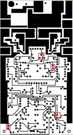
I hope that helps. I printed the board image on glossy high rez and held it up into the light like an x-ray; the only areas that raise concern are included in the attached. You may find if you have a desk lamp, it is good to place the PCB very close to the light bulb and study the trails.
Cheers,
Shawn.
edit: typos
Attachments
Most of the caps on your bill of material indicated by pF could be silver mica, shoot for 5% or 2% tolerance. 100V or 200V is typical.
Use all 1% resistors, non inductive if you can.
Low ESR for the electrolytics.
Many of the .1, .01 & .22 capacitors could be MKP WIMA type caps. Stay above 63V and most of these should be ok unless there is one or two across both rail supply voltages, then 100V or higher is necessary.
Since you have a left and right channel and they are he same PCB, I would be inclined to desolder all of the components from one of these boards, then I would spray it with flux remover and scan it right on your flat bed scanner, top and bottom, then you can e-ray the board image in photoshop by adjusting light levels and hue.
Cheers,
Shawn.
- Status
- This old topic is closed. If you want to reopen this topic, contact a moderator using the "Report Post" button.
- Home
- Amplifiers
- Solid State
- Marantz 510m Resurection