I want to mak a turn-on delay for a class-A amp, which is powered by 12V and has a capacitor on output (in series with speaker).
Can you help me make a circuit which would have cca 3sec turn-on delay and immediate turn off. The thing I need most help with is something to prevent activating the output too soon after someone switches it off and on again, probably something to discharge the timer cap or some latch.
For the immediate off I plan to use raw rectified voltage to power the relay, so when the transformer is switched off, the relay goes off too.
Your opinions?
Here is a simple one to start with(you'll find several more with a simple Google-search!)
http://www.epanorama.net/circuits/ampdelay.html
http://www.epanorama.net/circuits/ampdelay.html
kubeek said:Nordic and Rolf: those circuits dont match my needs, I want to have a latch, and the second one I can´t open.
lineup:
the supply will be 1x12Vac, and the delay can be any resonable time.
I get it, that you have a good quality relay
between the Output and Loudspeaker.
If so
One easy and very smart solution is this:
Get a 2-pole, 2-way relay
(we should use good quality relay, for not too high currents = low contact resistance)
When power on is sensed, a delay circuit is starting to load an electrolytic cap fed by a suitable resistor.
This by resistor current limited source, makes the cap take some time
to reach a certain voltage, at which a transistor starts to conduct (gets 0.7V across B-E)
and turns on relay for loudspeaker output.
pole #1 is for connect-disconnect speaker.
pole #2 is for discharge of the electrolytic cap
so when power is turned OFF,
this pole of relay will close a switch that discharge cap (via a suitable bleeder resistor, of course!)
... and this way the DELAY electrolytic cap is set to zero volt again.
So at power on, this will happen:
'cap', refers here to the electrolytic cap, that sets the delay time
1. The bleeder resistor discharger, is switched off, allowing for cap to load.
2. When voltage reach a certain level in cap, after 3-10 seconds like
- Loudspeaker is connected.
3. Power OFF, and 2 things will happen:
- Loudspeaker disconnected.
- Cap discharge resistor is connected.
4. Amplifier will be ready to be switch ON again, and delay will start from zero time.
I have seen such circuits.
For me or any other clever who wants to design such
it is not too difficult.
Now we know kubeek is using one single winding 12 VAC
for supply, we need almost no other information.
I might even be able to setup such a delay circuit
in my MultiSim to make sure it is working.
PS.
2-pole, 2-way relays are very useful.
The other pole can, for example, Turn on some indicator, LED
or do some other things , that could be needed at Power On.
For example, if one pre amplifier is SWITCHED ON,
the other pole will trigger a circuit that activates Mains Voltage to Power Amplifier!
And when pre amplifier is Switched OFF, the power amp is also SWITCHED OFF.
There are 3 types of these relays:
At no power:
type1- both relay poles are open, and closed at power on
type2- both relay poles are closed, and opened at power on
type3- one pole open and one pole closed
(type1 and type2 are the most common).
DS
Regards
lineup
K, I don't see, why the realy board would not work for what you want... what exactly do you think prevents this?
To use it to switch something off insted of on, you only need to change it so you use the 2 legs on the relay that are not connected now... the other 2 legs are "switch on side"
Also it runs fine off one rail... as long as you have between 5V and 16V to drive the timer chip... (lower voltage than 12V as per my example would require 6V relay)
Nordic, as I said in previous post, I cannot open the files in relayboard.zip, so I just don´t know what the circuit is.
lineup: thanks for the relay idea, I just needed the kick in the right way, I was thinking about discharging the cap with some jfet, but this is much better and simpler!
But as I think about it, I need two switches for stereo amp, so I will probably use dpdt relay for output and one small DIP relay for discharging the cap.
In eagle you need to click ratsnest to fill in the groundplane...
I made this PCB with a blackmarker by printing a mirror image from eagle. tapeing it to pcb, drilling the holes through the picture, remove paper and play connect the dots with the black marker...
I made this PCB with a blackmarker by printing a mirror image from eagle. tapeing it to pcb, drilling the holes through the picture, remove paper and play connect the dots with the black marker...
Attachments
Adjustable Time Delay for Loudspeaker, with 12V regulator
Yes, my information in that post(one relay with 2-pole 2-way) is useful, but not the correct solution in this case.
You have figured out the correct setup yourself:
One relay:
1 switch, Normally closed(at no power), for discharging TIME CAP.
One second relay:
Should be triggered by the TIME CAP, when reaches certain voltage.
As you say, this could be DPDT ( double pole, double throw )
= 2-pole 2-way
for control of BOTH channels output terminals to Speakers.
==========================================
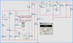
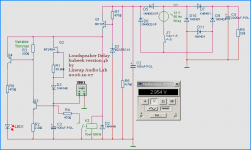
Below is my circuit.
In upper right corner is the main circuit,
12 Volt AC secondary, bridge rectifier, and Amplifier taking ~500mA idle (33 Ohm load)
From this 12 VAC, is a separate AC rectifier, using two 1N4002 (100V 1A).
They feed a simple 12 VDC regulator, with TO126 transistor output.
To load TIME CAP, I use a JFET CCS (adjusted for 50uA).
To discharge CAP, the 470ohm resistor.
Voltage across CAP is sensed by a TO92 Darlington.
( gain 2.000 - 4.000, takes almost no current from TIME CAP)
When voltage reach a certain level, after 3-5 seconds, for example,
this darlington(Q3) turns on Q4, which is the
driver for 12 Volt Loudspeaker relay.
For testing in this circuit, I use a LED that starts to light,
instead of the Loudspeaker relay.
---------------------------------------------------------------
By using a separate rectifier, two 1N4002,
it does not matter if the Main Big Caps in amplifier supply
are fully charged after switch OFF or discharged to any degree.
What is sensed is if the secondary AC of the transformer is ON.
For testing I used the AC ON-OFF SWITCH, J1, next to the 12V AC source.
The resistor R3, should be a Trim Pot, to adjust the time you want.
Also for getting longer time delays, you can Increase C3.
Formula I used for this timer: t = (C x V) / I
t, time in seconds
C = value of C3, 100uF
V = 3 Volt, after t seconds CAP has reached 3.0 Volt
I = Constant loading current = 50uA, by BF245A JFET
t = (100uF x 3) / 50uA
t ~ 6 seconds
Enjoy!
lineup
----------------------------------------
In my attached circuit, the LED was Turned ON
at about 2.992V across the TIME Cap, C3.
There are some smaller adjustments that might be needed for suit your needs.
But I think, in basic idea, this circuit is good,
has got very good precision, as well as
the feature with a 12 Volt regulator for relays is nice!
kubeek said:
lineup: thanks for the relay idea, I just needed the kick in the right way, I was thinking about discharging the cap with some jfet, but this is much better and simpler!
But as I think about it,
I need two switches for stereo amp, so I will probably use dpdt relay for output and one small DIP relay for discharging the cap.
kubeek said:So here is what I made: supply is full-rectified AC, cca 12-15V.
Time delay ON for 15Vpp is 3s, resetting time is 10ms.
Yes, my information in that post(one relay with 2-pole 2-way) is useful, but not the correct solution in this case.
You have figured out the correct setup yourself:
One relay:
1 switch, Normally closed(at no power), for discharging TIME CAP.
One second relay:
Should be triggered by the TIME CAP, when reaches certain voltage.
As you say, this could be DPDT ( double pole, double throw )
= 2-pole 2-way
for control of BOTH channels output terminals to Speakers.
==========================================
Below is my circuit.
In upper right corner is the main circuit,
12 Volt AC secondary, bridge rectifier, and Amplifier taking ~500mA idle (33 Ohm load)
From this 12 VAC, is a separate AC rectifier, using two 1N4002 (100V 1A).
They feed a simple 12 VDC regulator, with TO126 transistor output.
To load TIME CAP, I use a JFET CCS (adjusted for 50uA).
To discharge CAP, the 470ohm resistor.
Voltage across CAP is sensed by a TO92 Darlington.
( gain 2.000 - 4.000, takes almost no current from TIME CAP)
When voltage reach a certain level, after 3-5 seconds, for example,
this darlington(Q3) turns on Q4, which is the
driver for 12 Volt Loudspeaker relay.
For testing in this circuit, I use a LED that starts to light,
instead of the Loudspeaker relay.
---------------------------------------------------------------
By using a separate rectifier, two 1N4002,
it does not matter if the Main Big Caps in amplifier supply
are fully charged after switch OFF or discharged to any degree.
What is sensed is if the secondary AC of the transformer is ON.
For testing I used the AC ON-OFF SWITCH, J1, next to the 12V AC source.
The resistor R3, should be a Trim Pot, to adjust the time you want.
Also for getting longer time delays, you can Increase C3.
Formula I used for this timer: t = (C x V) / I
t, time in seconds
C = value of C3, 100uF
V = 3 Volt, after t seconds CAP has reached 3.0 Volt
I = Constant loading current = 50uA, by BF245A JFET
t = (100uF x 3) / 50uA
t ~ 6 seconds
Enjoy!
lineup
----------------------------------------
In my attached circuit, the LED was Turned ON
at about 2.992V across the TIME Cap, C3.
There are some smaller adjustments that might be needed for suit your needs.
But I think, in basic idea, this circuit is good,
has got very good precision, as well as
the feature with a 12 Volt regulator for relays is nice!
Attachments
okay
here is a better image
with the correct value, 100uF for C3 = TIME CAP
for comments, see my previous post above
Regards
lineup
Lineup Audio Lab
http://lineup.awardspace.com/
here is a better image
with the correct value, 100uF for C3 = TIME CAP
for comments, see my previous post above
Regards
lineup
Lineup Audio Lab
http://lineup.awardspace.com/
Attachments
kubeek said:Nice circuit, but I will stay with my design.
What do you think about that one?
Your circuit. If it works every time.
Then No problem.
To be honest, I did not try to explore it very much.
It looked a bit more advanced, using Op-Amps and all ..
Not my style.
I would prefer my own more simple and discrete circuit.
And I hope somebody will have good use for
kubeek-delay_4b
... because it is good.
Good Luck with your delay, kubeek.
My mission and hours( half a day ) of work at this project
... is over now.
lineup
 moving on from here to new interesting challenges
Lineup Audio Constructions
... circuits to fancy & trust
- Status
- This old topic is closed. If you want to reopen this topic, contact a moderator using the "Report Post" button.
- Home
- Amplifiers
- Solid State
- Turn on delay for single-railed amp