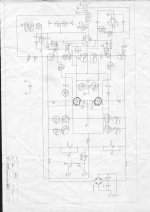
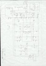
This is a rarely used topology, but it is in fact grounding the collectors and swinging the whole (floating) power supply as the output signal. This does complicate things regarding the power supply of the driver, which you can see in the schematic. Still, it would help if the drawing was clearer (without the circled components).
WolfgangL said:i got two amp modules where all TO3 outputs are mounted on a heatsink WITHOUT any isolator. The case of TO3 is collector, so all collectors shorted to ground. Will this work ?
TO3 case is = Collector
TO3 have no Pin for Collector
TO3 have B and E pin, only. Only TWO pins
So if output is Common Collector
and you have 4 TO3 power transistors at heatsink
all their Collectors are Connected.
This makes you need no Insulator Bricks ( isolator )
but you have to be careful
and make sure HEATSINK is isolated from GROUND
or any other junction in the amplifier!
Because
if heatsink, common collector output,
in contact with GROUND or other point
= SHORTCUT
Re: Re: END200 who knows this design ?
Ehhhh.... lineup, my friend, look at the schematic before posting") Otput is indeed common collector, and in this topology, it MUST be tied to ground.
Otput is indeed common collector, and in this topology, it MUST be tied to ground.
If you think about it, collectors are also coupled in a regular topology, it's just that they are coupled through x volts of a power supply, while emitters are coupled through zero volts (simplified). In this design, emitters are coupled through x volts and collectors through zero voltas. Actually, you could theoretically couple all of themeither way as long as you observe that there is the necessary x volts in the complete circuit through transistors, load and power supplies, and of course that the load sees no AC. For instance, in a circlotron amp (like Sumo), each emitter is coupled to each oposing collector through x/2 volts of the total power supply. It's really all the same thing, just the places of the components change around the complete output circuit. It is even possible to make a bridged amplifier in the same manner, see 'grounded bridge' topology.
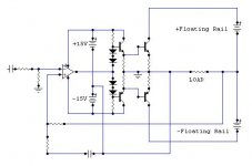
This particular amp runs the output transistors as common C (i.e. followers) but the positions of the power supply and the load are reversed. This means that:
1) The output is the center point of the power supply (which in this design is derived by AC coupling through the filter caps, note single winding transformer with no center tap).
2) The common collectors are the ground reference point, so NO insulation here, it MUST be grounded. If not, it won't work, perhaps destructively.
3) Like on the more common topologies, the output voltage is developed on the emitters, but in order to compensate for the grounding of the collectors, the power supply has been moved around so that the load sees no DC. In effect, the power supply is 'floating' WRT ground, and the output transistors 'move' it up and down WRT ground by the amopunt of output voltage - hence developing the output, which is why it is not coupled to the ground node at all.
4) This presents a problem for the input stage since it still has to be powered in a more or less conventional manner. because of this, the emitters of the outputs have diodes that are used to suypply power to the driver stages, as the 'moving' of the supply requires additional rectification to get ground referenced power. normally, this would be supplied by an extra winding on the power transformer, but the designers decided to cut a corner or two here.
The whole design is intriguing, and as far as i can surmise, the reason for it was to provide very good reliability, without sacrificing too much to complexity. Think about it: you can mount output transistors without mica, potentially reducing thermal resistance from output transistors to heatsink to a minimum. Also, the AC coupling prevents speakers from blowing if the output fails.
lineup said:...if output is Common Collector
and you have 4 TO3 power transistors at heatsink
all their Collectors are Connected.... make sure HEATSINK is isolated from GROUND
or any other junction in the amplifier!... Because
if heatsink, common collector output,
in contact with GROUND or other point
= SHORTCUT
Ehhhh.... lineup, my friend, look at the schematic before posting
Otput is indeed common collector, and in this topology, it MUST be tied to ground.If you think about it, collectors are also coupled in a regular topology, it's just that they are coupled through x volts of a power supply, while emitters are coupled through zero volts (simplified). In this design, emitters are coupled through x volts and collectors through zero voltas. Actually, you could theoretically couple all of themeither way as long as you observe that there is the necessary x volts in the complete circuit through transistors, load and power supplies, and of course that the load sees no AC. For instance, in a circlotron amp (like Sumo), each emitter is coupled to each oposing collector through x/2 volts of the total power supply. It's really all the same thing, just the places of the components change around the complete output circuit. It is even possible to make a bridged amplifier in the same manner, see 'grounded bridge' topology.
This particular amp runs the output transistors as common C (i.e. followers) but the positions of the power supply and the load are reversed. This means that:
1) The output is the center point of the power supply (which in this design is derived by AC coupling through the filter caps, note single winding transformer with no center tap).
2) The common collectors are the ground reference point, so NO insulation here, it MUST be grounded. If not, it won't work, perhaps destructively.
3) Like on the more common topologies, the output voltage is developed on the emitters, but in order to compensate for the grounding of the collectors, the power supply has been moved around so that the load sees no DC. In effect, the power supply is 'floating' WRT ground, and the output transistors 'move' it up and down WRT ground by the amopunt of output voltage - hence developing the output, which is why it is not coupled to the ground node at all.
4) This presents a problem for the input stage since it still has to be powered in a more or less conventional manner. because of this, the emitters of the outputs have diodes that are used to suypply power to the driver stages, as the 'moving' of the supply requires additional rectification to get ground referenced power. normally, this would be supplied by an extra winding on the power transformer, but the designers decided to cut a corner or two here.
The whole design is intriguing, and as far as i can surmise, the reason for it was to provide very good reliability, without sacrificing too much to complexity. Think about it: you can mount output transistors without mica, potentially reducing thermal resistance from output transistors to heatsink to a minimum. Also, the AC coupling prevents speakers from blowing if the output fails.
Re: Re: Re: END200 who knows this design ?
I was fully aware of the unusual circuitry here. With Grounded Collectors.
It is such a strange creature, I wont even bother to understand the benefits
... hard enough even with a perfect schematic, I would think.
My comment was more of a general advice.
When we can use no isolators for TO3,
is in 49/50 cases,
when common collector point used as output positive terminal.
And when and if we do, be warned!,
we have to insulate heatsink instead
.. to avoid risk for SHORTCUT Disaster
lineup
ilimzn said:
Ehhhh.... lineup, my friend, look at the schematic before posting
I was fully aware of the unusual circuitry here. With Grounded Collectors.
It is such a strange creature, I wont even bother to understand the benefits
... hard enough even with a perfect schematic, I would think.
My comment was more of a general advice.
When we can use no isolators for TO3,
is in 49/50 cases,
when common collector point used as output positive terminal.
And when and if we do, be warned!,
we have to insulate heatsink instead
.. to avoid risk for SHORTCUT Disaster
lineup
hello thanks to you all for your engagment
Hi ilimzn
I start to understand how this design will work.
But i have never seen an circuit like this before . Why it is so rare ? If you would give me your email addr i will mail you the originale scheme but it´s about 13 MB.
It is a class A/B or what amp ?
Hi ilimzn
I start to understand how this design will work.
But i have never seen an circuit like this before . Why it is so rare ? If you would give me your email addr i will mail you the originale scheme but it´s about 13 MB.
It is a class A/B or what amp ?
Re: Re: Re: Re: END200 who knows this design ?
True... although, amps where the collector is the common output point are quite rare - as you say 49 out of 50 times, emitters are tied together and there is some voltage on the colelctors/cases. Coupled collectors work the output pair as common source, most often in a CFP arrangement. Of course, because the common point is not goround then, it has to be insulated. Grounded collectors, this amp is the first that I have seen using them. There are some grounded sources LFET designs (LFETs have source on case, unlike other MOSFETs that have drain), these also work LFETs as common source.
It could be any of A, AB, or B - there seem to be pots to set bias current. The topology does not dictate any speciffic mode of operation.
I would very much appreciate a better readable schematic, as it is very interesting. I would be thankful if you can send it to ilimzn*at*hotmail*dot*com, I can try to edit it and post here.
@Mariodas,
Not sure there are any inherent sonic advantages - in principle it's the same just 'upside-down' from the usual, in a way. In fact, because the input stages are supplied by essentially rectifying output voltage, there may be disadvantages in this particular embodyment (the supply could, however, be done differently and the problems avoided).
I can't say anything about the power rating as I cannot read the voltage of the transformer or power lines, but I am guessing well over 100W due to the output transistors and usage of two pairs of them.
lineup said:My comment was more of a general advice.
When we can use no isolators for TO3,
is in 49/50 cases, when common collector point used as output positive terminal and when and if we do... we have to insulate heatsink instead to avoid risk for SHORTCUT Disaster
[/B]
True... although, amps where the collector is the common output point are quite rare - as you say 49 out of 50 times, emitters are tied together and there is some voltage on the colelctors/cases. Coupled collectors work the output pair as common source, most often in a CFP arrangement. Of course, because the common point is not goround then, it has to be insulated. Grounded collectors, this amp is the first that I have seen using them. There are some grounded sources LFET designs (LFETs have source on case, unlike other MOSFETs that have drain), these also work LFETs as common source.
Originally posted by WolfgangL
Hi ilimzn
I start to understand how this design will work.
But i have never seen an circuit like this before . Why it is so rare ? If you would give me your email addr i will mail you the originale scheme but it´s about 13 MB.
It is a class A/B or what amp ?
It could be any of A, AB, or B - there seem to be pots to set bias current. The topology does not dictate any speciffic mode of operation.
I would very much appreciate a better readable schematic, as it is very interesting. I would be thankful if you can send it to ilimzn*at*hotmail*dot*com, I can try to edit it and post here.
@Mariodas,
Not sure there are any inherent sonic advantages - in principle it's the same just 'upside-down' from the usual, in a way. In fact, because the input stages are supplied by essentially rectifying output voltage, there may be disadvantages in this particular embodyment (the supply could, however, be done differently and the problems avoided).
I can't say anything about the power rating as I cannot read the voltage of the transformer or power lines, but I am guessing well over 100W due to the output transistors and usage of two pairs of them.
Hi Folks,
I was surprised to see that all of you members donot know about this circuit and its functioning........
Its a copy from QSC clan of amplifiers.....
Its GROUNDED COLLECTOR AMPLIFIER
It features no Insulators as the Collectors are Grounded, AC COUPLED output[No DC TO speakers]
The power supply rails are Floating......also
Its very common design not rare one...
Behringer copies it in EP1500 and EP2400 amps
QSC uses it because Patrick Quilter[CEO OF QSC] first used this topology and he still uses this topology in his amps...
Its very reliable ..and serves as a CORE DESIGN of majority of QSC amplifiers
It also features Averaging Output Short Circuit Protection....
Its Class-AB and some present day models of QSC adopted it in Class-H as well ......
Have a look at these links.....
http://www.qscaudio.com/support/library/schems/Discontinued/USA Series/usa370.pdf
http://www.qscaudio.com/support/library/schems/Current/ISA Series/ISA450.pdf
http://www.qscaudio.com/support/library/schems/Current/RMX Series/rmx850.pdf
regards,
K a n w a r
Leolabs said:If I was not mistaken,some Hafler amps do use such topology.
Yes Hafler amp combine "Transnova" and implement GROUNDED SOURCE AMPLIFIER with Lateral Mosfets.....
BTW: Few years ago, I have also made GROUNDED EMITTER as well as GROUNDED DRAIN AMPLIFIER....The frontend is very easy to design just with a single opamp and low voltage drivers to control a Highvoltage output stage.....
K a n w a r
Workhorse said:
BTW: Few years ago, I have also made GROUNDED EMITTER as well as GROUNDED DRAIN AMPLIFIER....The frontend is very easy to design just with a single opamp and low voltage drivers to control a Highvoltage output stage.....
K a n w a r
Interesting!Can you show us your design???
- Status
- This old topic is closed. If you want to reopen this topic, contact a moderator using the "Report Post" button.
- Home
- Amplifiers
- Solid State
- END200 who knows this design ?