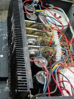
Ok, this sort of follows on from another thread where I was asking about heatsinking this setup here.
I've bought two J50/k175 maplin modules in kit form, and all the bits have been soldered to the PCB.
I've also got the caps, toroid, and rectifier, can I plan to use it all as a sub amp. The only thing is, my sub is 4ohm, as it's a car audio one.
Now, if I run this bridged, it will mean this it will run at 2 ohms, and I don't think the J50/k175 combo is capable of that is it?
Is there a way I can bridge this while keeping this at 4 ohms? Or is there a simple mod I could to to get more than 150w at 4 ohms?
My sub is capable of 400w rms, so I'd like to get close to this if possible.
400W/4R is 14A, three pair of J56/K176 on about ±90V or so.
This describes a Hafler DH500, a commercial 400W/4R amplifier. It had a large fan-cooled tunnel, and still ran quite warm. Later they bumped it to four pair per channel (XL-600).
The XL-280 used three pair of the J50/K135 on a lower voltage to do 400W in bridge mode (time may be thermally limited to several minutes). About ±50V would be right for 400W/4R in bridge mode.
How many outputs do those Maplin modules have?
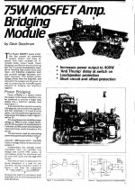
VERY interested. Do you have any more info or pics? I've sent you an e-mail also.poynton said:Maplin did a bridging module for this amp.
I seem to remember it gave a rated output of 400W into 2ohm.
I may have 1 somewhere if you are interested.
Andy
")
Well this sounds ideal to me, as my toroid is ±50V. The only thing is, as sub is 4ohms unbridged, so when I run it bridged, it would run at 2 ohms. If I can somehow find a way of getting these J50/K135's to run at 2 ohms, then I'll be more than happy. I'm not aware so far of anyone running these at 2 ohms, but I'm sure it must be possible with the right bits...djk said:The XL-280 used three pair of the J50/K135 on a lower voltage to do 400W in bridge mode (time may be thermally limited to several minutes). About ±50V would be right for 400W/4R in bridge mode.
Also, I've only got 2 pairs of J50/K135's. I might be able to get more tho, but they wouldn't be matched - I'm not sure if this will be much of an issue tho, as it's only driving a sub.
Also, heatsinking won't be a problem. I recently aquired over 20kg of alu heatsinks.
I've got 2 modules, and each module has one speaker output.djk said:How many outputs do those Maplin modules have?
MikeHunt79 said:
VERY interested. Do you have any more info or pics? .
Hi.
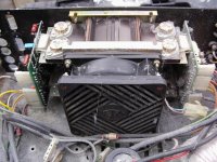
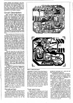
This photo may give you an idea of heatsinking for the Maplin modules. The bridging units are on the RHS x2.
[This was the mid-range stereo amp for a disco]
Andy
Attachments
Thanks for the pics... they are worth more than 100 words.poynton said:
This photo may give you an idea of heatsinking for the Maplin modules. The bridging units are on the RHS x2.
Do you know if either of these amps are 2 ohms stable? Or have any more info or specs? I'd basically like to do a 1 channel version of this amp, with 1 pair of modules, instead of a 2 channel one with 4 modules. I'm guessing it does around 300w per channel?I've got heatsink around the same size as that, but the fins are twice as long, so I'm sure I shuold be fine heatwise. It's good to see what the professionals are using tho.
Let me make this simple:
There is no way a single pair of J50/K135 will work into 2 ohms the way you want it to.
J50/K135 are 7A parts. Maximum dissipation is 100W at case temperature of 25C, which, using normal heatsinking methods implies a near infinite heatsink (a quick calculation shows a total thermal resistance of 1.25K/W, considering the resistance of the channel to case plus the isolation material, the heatsink comes out as something below 0.1K/W - this would be enormous.
RdsON is quite high for lateral MOSFETs - about 1 ohm, but this will already imply heavy clipping in an audio amp. Since the amplifier module uses the same power supply for both input and driver stage as for the output FETs, the figure in the datasheet giving saturation voltage at Vgd=0 applies, at 7A this is 12V max - already 84W of dissipation just at the peak of the waveform, and that's not the maximum. Meanwhile, at 7A, you have 14V into 2 ohms PEAK. This means each amp in the bridge contributes about 49W, so you get 98W into a bridged 4 ohm load, and should not use rail voltages higher than about 28V.
Consider what happens if you use the same quick and dirty calculation with a 4 ohm load: at 7A the voltage on the load is 28V, and the power 98W - from a SINGLE module, approximately the same power dissipated per module, but rails are about 42V. In other words, using two mudules bridged into a 4 ohm load gives you exactly the same maximum power just with twice the heat.
In other words, in order to get more power, you need an amplifier with more output FET pairs, although the situation would be slightly better if the output stage had about 12-14V lower power supply rails than the driver stage. And all of this is with a very much oversimplified calculation - real world will be much worse!
A single pair of J50/K135 on ±50V will only drive 100W/4R (if you can keep it cool).
100W/4R is at the maximum drain current for the device. The Rds over temperature for this part is 1R7, so the minimum voltage loss will be 12V (plus the front-end loss).
The Hafler DH-120 is built this way, uses ±52V, and did 90W/4R (time may be thermally limited to several minutes).
100W/4R is at the maximum drain current for the device. The Rds over temperature for this part is 1R7, so the minimum voltage loss will be 12V (plus the front-end loss).
The Hafler DH-120 is built this way, uses ±52V, and did 90W/4R (time may be thermally limited to several minutes).
MikeHunt79 said:Ok, gotcha. The only point in bridging these would be if you were driving an 8 ohm driver, on order to achieve a 4 ohm impedance.
I'll stick to a single driver for now, giving me 150w at 4 ohms.
See DJK's post - also, here are two important things to remember about loudspeakers:
1) Two speakers connected in series, driven by some nominal voltage, will give you the same loudness as one speaker driven by the same voltage, but they will only use half the power - this is because the same voltage is now developed over twice the load impedance, but is now driving twice the cone area! It may not be obvious, but this means that two speakers driven with 100W each will give you twice the loudness of one speaker driven by 200W. Of course, i am referring to loudness in linear terms, in practise, the perception of it is logarithmic.
2) Because of the said logarithmic perception of loudness, for each doubling of percieved loudness, you need to increase the pwoer TENFOLD. Therefore, you will find that the difference in loudness between 100 and 150W is almost negligible.
To add things up: you would need to feed 400W into a single woofer to make it as loud as two woofers fed 100W each. I believe this is quite relevant to your problem!
Oh, and BTW a 2x50VAC toroid will give you about 2x70V rectified DC unloaded. This is WAY too high for your application.
Hi Thermionic
Check this website out it is simple to build on vero board.
It's not Maplin but should work.
Bridging Adapter For Power Amps
Regards - Anthony
Check this website out it is simple to build on vero board.
It's not Maplin but should work.
Bridging Adapter For Power Amps
Regards - Anthony
Thanks, Anthony. I'm aware of numerous balancing buffers that should do the task well (and transformers). I asked because I wondered how Dave Goodman (Maplin amp's designer) would've done it, i.e. whether it'd be a balanced buffer out of typical IC apps. data, or idiosyncratic.
Cheers,
Justin
Cheers,
Justin
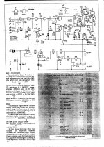
A double pair of J50/K135 on +75 V - 75 V (total 150 V )
gives 150 rms in 8 Ω, 250 rms in 4 Ω, and 360 rms in 2 Ω
it necesary to put power transformers more than gives the schematic (20 A per channel and +75 V - 75 ( total 150 )
I have build from 1991 perfect machine !!!!!!!!!!
gives 150 rms in 8 Ω, 250 rms in 4 Ω, and 360 rms in 2 Ω
it necesary to put power transformers more than gives the schematic (20 A per channel and +75 V - 75 ( total 150 )
I have build from 1991 perfect machine !!!!!!!!!!
- Status
- This old topic is closed. If you want to reopen this topic, contact a moderator using the "Report Post" button.
- Home
- Amplifiers
- Solid State
- Bridging Hitachi J50/k175 combo?