smoking-amp said:
The obvious fixups would be operating devices in regions where capacitance is either minimized or stable.
...or to shunt them by resistors, more rationally utilizing output power of previous stage, also loading the previous stage with more linear load. In turn, it will result in less deep NFB with the same number of active elements.
")
"...or to shunt them by resistors..."
Yup, local linearizations, degenerations...
Any opinion on the back- to- back varicaps controlled by inverted audio signal idea?
( to neutralize capacitance variation of problematic devices)
OK, obviously it will add capacitance and decrease bandwidth, but how about we use it as the miller cap for compensation. Two birds with one stone!
Don
smoking-amp said:"...or to shunt them by resistors..."
Yup, local linearizations, degenerations...
More than. Assuming peaceful coexistance of 2 and more stages instead of "one stage serves another" like in common approach of thinking.
Any opinion on the back- to- back varicaps controlled by inverted audio signal idea?
( to neutralize capacitance variation of problematic devices)
OK, obviously it will add capacitance and decrease bandwidth, but how about we use it as the miller cap for compensation. Two birds with one stone!
Don
Sounds good if you have an "anti-varicap".
Speaking of non-harmonics distortions, I can't imagine any source of them except oscillations, or at least ringings.
"Sounds good if you have an "anti-varicap". "
Hmmm, yes, Vas output signal levels would be too big to counter their effect by a control signal on back-to-back vari-caps.
How about we use a cascode for the VAS stage (with a little resistance for limited Volt swing between) and put the varicap miller on the lower transistor.
Or..., how about we just connect a varicap from an inverted audio point to the VAS input. Like a neutralization cap. for RF. That way we knock out the device internal junction cap. effect and we just use an external discrete cap for the total Miller compensation then.
Trouble is the two (varicap and junction cap )are not tracking each other capacitance wise with the inverted signals on them.
I think the basic problem here is that one cannot vary the control signal at the same rate as the audio signal. Darn. Back to back varicaps only work for slow tuning applications. Oh well.... we really do need anti-varicaps.
No, wait! We use the cascoded VAS but put some inverted audio signal on the upper device base or gate. That way we can invert the non-linear capacitance effects of the lower device. Hmmm, maybe..., probably still has the capacitance tracking problem.
Don
smoking-amp said:"Sounds good if you have an "anti-varicap". "
probably still has the capacitance tracking problem.
Don
By the way, about anti-varicaps, anti-distortions, anti-harmonics... If to take a symmetrical triangle signal (wide spector of uneven harmonics) and to limit it using couple of diodes we may get a signal very close to sinusoidal... Non-linear approximation of the function. The same way the linear function may be obtained using non-linear parts, as I demonstrated some time ago.
Re: Re-entrant feedback distortion
Hi, i once showed that effect nicely in sims with a virtual amplifier. (Creating 2nd harmonic only openloop)
http://www.diyaudio.com/forums/showthread.php?postid=843339#post843339
You might ignore my assumptions about local feedback.
It looks like that this effect can get quite severe if feedback is misused to compensate lousy openloop behaviour of an amp.
But, if openloop distortion is low enough and feedback high enough, this effect becomes too small to care.
Mike
Bob Cordell said:What you are really discussing here is so-called re-entrant distortion in feedback amplifiers. It is absolutely true that it exists, but one needs to do the math and do measurements to see how big an issue it is.
Hi, i once showed that effect nicely in sims with a virtual amplifier. (Creating 2nd harmonic only openloop)
http://www.diyaudio.com/forums/showthread.php?postid=843339#post843339
You might ignore my assumptions about local feedback.
It looks like that this effect can get quite severe if feedback is misused to compensate lousy openloop behaviour of an amp.
But, if openloop distortion is low enough and feedback high enough, this effect becomes too small to care.
Mike
Re: Re: Re-entrant feedback distortion
Tris "misuse" is one of the main reasons of NFB usage (except 2 more reasons of similar misuse).
The phenomena of higher order of distortions is not product of feedback itself, it is product of time delays.
MikeB said:
Hi, i once showed that effect nicely in sims with a virtual amplifier. (Creating 2nd harmonic only openloop)
http://www.diyaudio.com/forums/showthread.php?postid=843339#post843339
You might ignore my assumptions about local feedback.
It looks like that this effect can get quite severe if feedback is misused to compensate lousy openloop behaviour of an amp.
But, if openloop distortion is low enough and feedback high enough, this effect becomes too small to care.
Mike
Tris "misuse" is one of the main reasons of NFB usage (except 2 more reasons of similar misuse).
The phenomena of higher order of distortions is not product of feedback itself, it is product of time delays.
Re: Re: Re: Re-entrant feedback distortion
That's a very common misbelieve, "propagation delay" has absolutely nothing to do with that. This higher order distortion happens the same amount without any phasehift. Or did you see any "delaying" device ?
The phenomena of higher order distortions is ONLY product of feedback itself ! Think of this effect like that the error signal gets distorted again. The phaseshifted errorsignal seems to cause nothing.
This "propagation delay" thing is a fairy tale, such thing does not exist. There is no delay, only phasehift. A minor but important difference.
"misuse" = horribly high open loop distortion...
Mike
Wavebourn said:
Tris "misuse" is one of the main reasons of NFB usage (except 2 more reasons of similar misuse).
The phenomena of higher order of distortions is not product of feedback itself, it is product of time delays.
That's a very common misbelieve, "propagation delay" has absolutely nothing to do with that. This higher order distortion happens the same amount without any phasehift. Or did you see any "delaying" device ?The phenomena of higher order distortions is ONLY product of feedback itself ! Think of this effect like that the error signal gets distorted again. The phaseshifted errorsignal seems to cause nothing.
This "propagation delay" thing is a fairy tale, such thing does not exist. There is no delay, only phasehift. A minor but important difference.
"misuse" = horribly high open loop distortion...
Mike
Re: Re: Re: Re: Re-entrant feedback distortion
Can you show me please how pure additions/substitutions of the function of any nonlinear complexity can change it's complexity?
If your "horribly distortion" means phase shifts I agree with you that it will cause change of the transfer function.
MikeB said:
The phenomena of higher order distortions is ONLY product of feedback itself ! Think of this effect like that the error signal gets distorted again. The phaseshifted errorsignal seems to cause nothing.
This "propagation delay" thing is a fairy tale, such thing does not exist. There is no delay, only phasehift. A minor but important difference.
"misuse" = horribly high open loop distortion...
Mike
Can you show me please how pure additions/substitutions of the function of any nonlinear complexity can change it's complexity?
If your "horribly distortion" means phase shifts I agree with you that it will cause change of the transfer function.
Re: Re: Re: Re: Re: Re-entrant feedback distortion
Simply study my simple circuit. A transfer curve creating 2nd harmonic only, will create a 3rd and 4th harmonic when applied a 2nd time. That's what feedback does, just not only once, an unlimited times simultaneously.
That's why Bob called it "Re-entrant feedback distortion"
Feedback can not cancel distortions, only attenuate. (Unless you have infinite openloopgain maybe)
I am not good enough in mathematics to prove it with formulas.
Mike
Wavebourn said:
Can you show me please how pure additions/substitutions of the function of any nonlinear complexity can change it's complexity?
Simply study my simple circuit. A transfer curve creating 2nd harmonic only, will create a 3rd and 4th harmonic when applied a 2nd time. That's what feedback does, just not only once, an unlimited times simultaneously.
That's why Bob called it "Re-entrant feedback distortion"
Feedback can not cancel distortions, only attenuate. (Unless you have infinite openloopgain maybe)
I am not good enough in mathematics to prove it with formulas.
Mike
Re: Re: Re: Re: Re: Re-entrant feedback distortion
you haven't looked at our sims, in post #18 I point to a pure sqaure law behavioral voltage source, no delay, no compensation cap only a constant feedback factor around a nonlinearity - which clearly shows the reduction in distortion vs open loop and and the infinite series of new harmonic products
http://www.diyaudio.com/forums/showthread.php?s=&postid=920583&highlight=#post920583
the solution of the feedback equation including the sqare law nonlinearity is expressed as a infinite Taylor series in the input voltage - a simple consequence of a nonlinear transformation of the single sine periodic input signal is that the output is a infinite Fourier series of the input frequency
Cherry shows this very well in "Estimates of Nonlinear Distortion in Feedback Amplifiers" JAES v48 #4 4/2000
Baxandall presented similar feedback distortion math in wireless world in 1979, even earlier tube feedback amplifier distortion product expansions date at least to the 50's
Wavebourn said:
The phenomena of higher order of distortions is not product of feedback itself, it is product of time delays.
Wavebourn said:
Can you show me please how pure additions/substitutions of the function of any nonlinear complexity can change it's complexity?
If your "horribly distortion" means phase shifts I agree with you that it will cause change of the transfer function.
you haven't looked at our sims, in post #18 I point to a pure sqaure law behavioral voltage source, no delay, no compensation cap only a constant feedback factor around a nonlinearity - which clearly shows the reduction in distortion vs open loop and and the infinite series of new harmonic products
http://www.diyaudio.com/forums/showthread.php?s=&postid=920583&highlight=#post920583
the solution of the feedback equation including the sqare law nonlinearity is expressed as a infinite Taylor series in the input voltage - a simple consequence of a nonlinear transformation of the single sine periodic input signal is that the output is a infinite Fourier series of the input frequency
Cherry shows this very well in "Estimates of Nonlinear Distortion in Feedback Amplifiers" JAES v48 #4 4/2000
Baxandall presented similar feedback distortion math in wireless world in 1979, even earlier tube feedback amplifier distortion product expansions date at least to the 50's
Re: Re: Re: Re: Re: Re: Re-entrant feedback distortion
Ok, let's Uout = Uin*K1 + Uin^2*K2,
where K1 = coefficient of linear voltage amplification, K2 - coefficient of the 2'nd order voltage amplification, Uout is output voltage, Uin is input voltage.
Open loop coefficient is:
Kol = (Uin*K1 + Uin^2*K2)/Uin = K1+Uin*K2.
Now, let's apply a feedback, so
closed loop coefficient is
Kcl = (Uin *(K1+Uin*K2) + Uin(K1+Uin*K2)*Kfb)/Uin
= K1 +Uin*K2 +K1*Kfb + Uin*K2*Kfb
i.e.
Kcl = K1 * (1 + Kfb) + Uin*K2*(1+Kfb)
i.e. I do not see any additional order except the second one we had already.
Where is my mistake?
MikeB said:
Simply study my simple circuit. A transfer curve creating 2nd harmonic only, will create a 3rd and 4th harmonic when applied a 2nd time. That's what feedback does, just not only once, an unlimited times simultaneously.
That's why Bob called it "Re-entrant feedback distortion"
Feedback can not cancel distortions, only attenuate. (Unless you have infinite openloopgain maybe)
I am not good enough in mathematics to prove it with formulas.
Mike
Ok, let's Uout = Uin*K1 + Uin^2*K2,
where K1 = coefficient of linear voltage amplification, K2 - coefficient of the 2'nd order voltage amplification, Uout is output voltage, Uin is input voltage.
Open loop coefficient is:
Kol = (Uin*K1 + Uin^2*K2)/Uin = K1+Uin*K2.
Now, let's apply a feedback, so
closed loop coefficient is
Kcl = (Uin *(K1+Uin*K2) + Uin(K1+Uin*K2)*Kfb)/Uin
= K1 +Uin*K2 +K1*Kfb + Uin*K2*Kfb
i.e.
Kcl = K1 * (1 + Kfb) + Uin*K2*(1+Kfb)
i.e. I do not see any additional order except the second one we had already.
Where is my mistake?
Wavebourn said:
Where is my mistake?
Your mistake was assuming a constant feedback, taking Kfb as a constant.
Remember that closedloop is not fixed set by resistor network.
Cg = K / (1 + K/Og)
Where:
Cg = Closed loop gain
Og = Open loop gain
K = factor from resistor network (the only constant here)
Openloop unlinearity is nothing else than a "modulated" open loop gain, giving a gain dependent on the level amplified.
-> Kfb = Og / (K / (1 + K/Og))
-> Kfb = (Og * (1 + K/Og)) / K
-> Kfb = (Og + K) / K
This means, you have to enter the transfer function for Og. (The modulated gain)
Then, you get:
Cg = K / (1 + K/(K1+Uin*K2))
This function is no longer a pure second order, it's an endless supply of harmonics.
Gladly, making Og large enough, you get nearly Cg = K / 1. (=linear)
This makes amplifiers using 6db of feedback absurd. They lower the original harmonic by 6db and create plenty of new harmonics.
I forgot, fundamental feedback math is very simple and immediately shows the concept and "flaws" of nfb.
In other words: NFB converts the original transfer function to something different, but more linear.
Mike
MikeB said:
Your mistake was assuming a constant feedback, taking Kfb as a constant.
No, it is not a mistake. I assumed a "round horse in vacuum", i.e. just an ideal amp with 1'st and 2'nd order gain and linear input impedance, in such case feedback coefficient is constant and depends on a division ratio of the loop.
So, where was the mistake in my simple calculations?
This means, you have to enter the transfer function for Og. (The modulated gain)
Right.
Thank you!
Now, assume your very deep feedback plus non-linear phase delay...
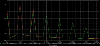
Here is the fft-plot of a nfb-modified transfer curve for transfer curve of y = x + x*x*0.2 (~10% 2nd harmonic)
NFB is set to unitygain with openloopgain of 10. (the result is scaled down by 10 for better fit)
You see how the 2nd harmonic is reduced factor 10, but as extra gift you get some really nice higher oder harmonics.
This example is exaggerated (but not unrealistic), openloop distortion with 10% and feedback factor of 20db is what i call "misuse".
The result nicely matches my virtual amp, this time just mathematical.
For comparison is the red plot, the openloop transfer.
Mike
Attachments
I wouldn't pretend to be any expert on this re-entrant calculation, but here is my shot at it:
Open loop gain: K1+K2*Uin
Closed loop: Uin=U0-Xout/K3 and Xout=(K1+K2*Uin)*Uin
K3 = Kfb and U0 is actual input signal
putting Uin eqn into Xout eqn gives:
Xout=K1(U0-Xout/k3) + K2(U0-Xout/k3)**2
separating by terms of Xout:
K2/K3*Xout**2 - (1+K1/K3+2*U0*K2/K3)*Xout +(K1*U0+K2*U0*U0) = 0
solving for Xout:
(2*K2/K3) * Xout= (1+K1/K3+2*U0*K2/K3) +/- SQRT[ (1+K1/K3+2*U0*K2/K3)**2 - 4K2/K3*(K1*U0+K2*U0*U0) ]
Seems likely this would require a lengthy Taylor series to describe it.
And this was just for a simple squared transfer function. Need Mathcad or something to properly convert this to a Taylor series.
Wonder if there is some magical transfer function that would give a simple Xout = U0+k*U0*U0 result. Then push-pull could be perfect.
Don
smoking-amp and MikeB;
I was wrong arguing against feedback as the pure source of higher order distortions because I always used deep feedback and all my observations were related to the main cause of higher order distortions in this case that is phase shift, especially non-linear one. It means, I never mis-used it as you said, so was blind about such case.
Thanks again!
Wavebourn said:
Right.
Thank you!
No problem, explaining it helps me better understanding it.
Wavebourn said:
Now, assume your very deep feedback plus non-linear phase delay...
This is definitely way above my math skills...

I already tried hunting that, with null result. Feedback happily (how is that written ?) compensated/reduced phasehifts without obvious side effects.
The only interesting thing here seems PIM...
Don, i guess you can have things much simpler when looking at the nfb beeing a black box that simply follows the rule Cg = K / (1 + K/Og). This already gives you the result and the source for the new harmonics.
It looks like that the Taylor series is infinite.
Mike
Maybe one could design a fully assymetric amplifier that can only produce even harmonics (at least below some saturation level), then use two in push -pull form to cancel the even harmonics. Won't fix IMD problems though.
There are also some wide band phase shift networks used for SSB that can give cosines of all input sine signals, ie 90 degree phase shift for all signal components. Some interesting cancellations are possible mathematically if one runs these two signals through two identical amplifiers and sum the results. (sine**2 + cosine**2 = constant)
A linear transfer SIT device still looks the most promising approach. They aren't that difficult to make. Where are they?
Don
- Status
- This old topic is closed. If you want to reopen this topic, contact a moderator using the "Report Post" button.
- Home
- Amplifiers
- Solid State
- coherent noise and chaotic distortion