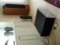
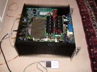
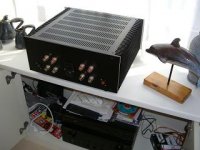
Here are some pictures of my amp (which I have called the 'Ovation 250'). Its a fully complementary design and this week end I finaaly got it running and driving my B&W703's. I spent 18 months designing it and prototyping over the last 3 or 4 years in between doing an MBA and moving to Japan recently. Final product you see here uses DSTHP PCB's. +-75 volt rails, 2.5KVA transformer and 100mFD of smoothing. I got the case from Fischer Elektronic (not impressed - it is a bit crude - I will send them some feedback) and still have to get a final front panel made. Uses 5 pairs MJL21193/94 per channel.
I fired it up and just used my iPod to try it out. Sounded very good to my ears (but I am biased) and compared to my Marantz PM68.
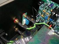
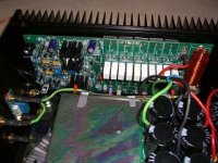
There is still a bit of refinement to do to - e.g. correct errors on the control board (this is uController based and does in-rush current limiting, thermal protection, DC offset, clipping indicator, output relay control), and a small mod I want to make to the VAS stage. The power supply will also be cleaned up. I expect these things to take another 3-6 months - I'm pretty busy at the minute.
I learnt a lot from this project about audio power amps - my background is in industrial electronics - linear systems design (TC amps, A-D, SMPS etc).
I have circuits in an Excel spread sheet but they are >100kb - I'll post them if someone tells me how to get them onto the forum.
I fired it up and just used my iPod to try it out. Sounded very good to my ears (but I am biased) and compared to my Marantz PM68.
There is still a bit of refinement to do to - e.g. correct errors on the control board (this is uController based and does in-rush current limiting, thermal protection, DC offset, clipping indicator, output relay control), and a small mod I want to make to the VAS stage. The power supply will also be cleaned up. I expect these things to take another 3-6 months - I'm pretty busy at the minute.
I learnt a lot from this project about audio power amps - my background is in industrial electronics - linear systems design (TC amps, A-D, SMPS etc).
I have circuits in an Excel spread sheet but they are >100kb - I'll post them if someone tells me how to get them onto the forum.
Attachments
Bonsai said:
I have circuits in an Excel spread sheet but they are >100kb - I'll post them if someone tells me how to get them onto the forum.
Upload here, and post link.
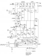
final circuit - the control board. Quite a few modes to this board so I will have to re-do it. Triacs thrown out and replaced with relays etc.
btw got the mains transformer specially would by Airlink before I left for Tokyo - very quiet and worth the money.
btw got the mains transformer specially would by Airlink before I left for Tokyo - very quiet and worth the money.
Attachments

")
darkfenriz,
Thanks for the comments.
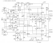
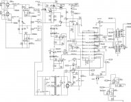
The rc filter on the bases of the drivers was included to overcome output stage oscillation - about 2 mHz if I recall correctly. Some designers take a cap straight from the base of the driver to the associated plus and minus rail - i.e. exclude the resistor. I did not find this was entirely successfull so added the resistor and that cured it - although it adds another pole in the response.
The 'rc' filter in the feeback network is part of the feedforward compensation scheme I used. The 47pf and 15k from the output of the driver stage back to the diff amp inverting input is also part of this scheme. This compensation approach is discussed in Self (though his implementation is different), Leach and I think was first proposed by Robert Dobkin of Natsemi about 30 years ago. Seems to work well. The 33pf caps across the emitter degeneration resistors give an additional 5-8 degress of phase margin (simulated).
I run the front end diff amp at 5mA per side to give fast rise and fall times - I think it would be quite hard to get this amp to slew limit.
I have not measured distortion yet - I'll get a decent sound card in the new year and try that.
Thanks for the comments.
The rc filter on the bases of the drivers was included to overcome output stage oscillation - about 2 mHz if I recall correctly. Some designers take a cap straight from the base of the driver to the associated plus and minus rail - i.e. exclude the resistor. I did not find this was entirely successfull so added the resistor and that cured it - although it adds another pole in the response.
The 'rc' filter in the feeback network is part of the feedforward compensation scheme I used. The 47pf and 15k from the output of the driver stage back to the diff amp inverting input is also part of this scheme. This compensation approach is discussed in Self (though his implementation is different), Leach and I think was first proposed by Robert Dobkin of Natsemi about 30 years ago. Seems to work well. The 33pf caps across the emitter degeneration resistors give an additional 5-8 degress of phase margin (simulated).
I run the front end diff amp at 5mA per side to give fast rise and fall times - I think it would be quite hard to get this amp to slew limit.
I have not measured distortion yet - I'll get a decent sound card in the new year and try that.
Good job! Very tidy construction.
I'm planning on using a uP at then heart of the (yet to be designed) control board for my current power amp project too (dc protection, timing for speaker de-thump, in-rush I limit control, HT supply power-up delay for valve heater warmup, etc).
Much better than having multiple RC timers.
http://www.diyaudio.com/forums/showthread.php?s=&threadid=91062&pagenumber=3
- Status
- This old topic is closed. If you want to reopen this topic, contact a moderator using the "Report Post" button.
- Home
- Amplifiers
- Solid State
- Ovation Amp