Hi all:
I recently read about National's new audio opamp - the LM4562.
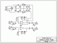
I got a few chips and decided that my first project would be a phono stage. I decided to build the example single gain block design provided in the datasheet.
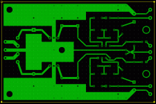
So, a little pcb layout work with PCB Express, some etching and drilling and I had a board. Some soldering and I had a circut. Power up and, well, Ill be d^&*ed - it works!
BUT (theres always one - at least) it hums.
It has a pronounced 60Hz hum that I cant identify the source of. Looking with the scope, the PS rails are clean, the input is clean, but there is a distinct AC hum on the output - about 15% of the total volume.
Can anyone suggest how I can find the source of this hum?
I would appreciate any suggestions.
I recently read about National's new audio opamp - the LM4562.
I got a few chips and decided that my first project would be a phono stage. I decided to build the example single gain block design provided in the datasheet.
So, a little pcb layout work with PCB Express, some etching and drilling and I had a board. Some soldering and I had a circut. Power up and, well, Ill be d^&*ed - it works!
BUT (theres always one - at least) it hums.
It has a pronounced 60Hz hum that I cant identify the source of. Looking with the scope, the PS rails are clean, the input is clean, but there is a distinct AC hum on the output - about 15% of the total volume.
Can anyone suggest how I can find the source of this hum?
I would appreciate any suggestions.
Attachments
Since you have a full bridge, I'd expect the hum to be 120Hz + harmonics.
I don't see any bypass caps on that chip...
Could you please explain = bypass caps on which chip, where??
The datasheet indicates that the 4562 has a PSSR of >110db. Would this not eliminate any ripple from the rails getting into the output? And, there is no mention of bypass caps in the applications section.
What am I missing?
- Your PCB layout contains several ground loops and it's overall quite poor. As a result, PSU capacitor ripple current from the unregulated side is being directly fed as voltage into the inverting input of the op-amps and amplfiied with the full RIAA gain.
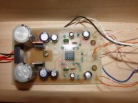
- A phono preamplifier involves sub-milivolt signals and high impedance nodes, thus it requires careful electrostatic shielding, yet your PCB is attached to a bare wooden box. That's absolutely unsuitable.
- The 7912 regulator is not properly wired in the PCB mask shown.
I suggest starting a new PCB layout from scratch (conceptually the circuit is fine), but you have a lot to learn about PCB routing. You should have posted your layout here and asked for improvements before etching the PCB.
Tip: Read about star grounding techniques.
- Your PCB layout contains several ground loops and it's overall quite poor. As a result, PSU capacitor ripple current from the unregulated side is being directly fed as voltage into the inverting input of the op-amps and amplfiied with the full RIAA gain.
- A phono preamplifier involves sub-milivolt signals and high impedance nodes, thus it requires careful electrostatic shielding, yet your PCB is attached to a bare wooden box. That's absolutely unsuitable.
- The 7912 regulator is not properly wired in the PCB mask shown.
I suggest starting a new PCB layout from scratch (conceptually the circuit is fine), but you have a lot to learn about PCB routing. You should have posted your layout here and asked for improvements before etching the PCB.
Thanks, Eva - as you say, I have a lot to learn about pcb layout. This is my third attempt, the first two being non-critical ccts.
I am very happy to start over. Any suggestions on where to begin?
PS: I caught the error on the 7915 reg during the build and managed a work-around.
Jess
Fixed the hum
Hi all:
For those of you who might be interested how this turned out, I got the hum fixed.
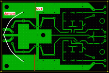
A freind offered a suggestion for a very simple mod (see PCB image. This killed the ground loop and the hum.
Initial listening impressions are: superb bass, very balanced and natural overall. Highs seem a bit reduced (but just a bit). This is probably due to my choice of eq caps.
Next one I will get first-rate caps and, in the meantime I will be working on my PCB skills. If anyone has any suggestions where to get beginner's info on PCB layout, I would appreciate it.
Onward and upward (hopefully).
Jess
Hi all:
For those of you who might be interested how this turned out, I got the hum fixed.
A freind offered a suggestion for a very simple mod (see PCB image. This killed the ground loop and the hum.
Initial listening impressions are: superb bass, very balanced and natural overall. Highs seem a bit reduced (but just a bit). This is probably due to my choice of eq caps.
Next one I will get first-rate caps and, in the meantime I will be working on my PCB skills. If anyone has any suggestions where to get beginner's info on PCB layout, I would appreciate it.
Onward and upward (hopefully).
Jess
Attachments
making boards
On my first board - I sent out to have my board done - by Professionals. Requesting the 'work-up' for the project, my result was a Walk-Thru of the procedures for my board developement, the chips' placements - passive & active - and guidelines to make my OWN BOARDS in the Future.
All-In I spent $212 for Tutalage & Labor. Battery Power the Preamp boards and a simple B+ monitor. Shield all boards - regardless.
Ground ALL NEG - TO REAL GROUND. Drive a rebar into the ground if you have to.
Whatever You Preamplify - will REALLY be amp'ed - through your $500 250W amp !
Grampa Pre-Amp's in the basement - and cables that into his living room - so when he Blasts a song, the Preamp is not 'getting his feedback' !
-P-
Hi all:
For those of you who might be interested how this turned out, I got the hum fixed.
A freind offered a suggestion for a very simple mod (see PCB image. This killed the ground loop and the hum.
Initial listening impressions are: superb bass, very balanced and natural overall. Highs seem a bit reduced (but just a bit). This is probably due to my choice of eq caps.
Next one I will get first-rate caps and, in the meantime I will be working on my PCB skills. If anyone has any suggestions where to get beginner's info on PCB layout, I would appreciate it.
Onward and upward (hopefully).
Jess
Neat solution!!!!
- Status
- This old topic is closed. If you want to reopen this topic, contact a moderator using the "Report Post" button.
- Home
- Amplifiers
- Solid State
- Hum hunting - LM4562 Phono stage