hi friends!
here is an old amp from my socialistic era when i grew up in czechoslovakia
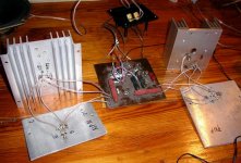
i had these circuit boards assembled and tested long time ago
(15 years perhaps?) so i thought why not to finish it
all original including power output transistors
its happily working now, i just have few questions
one pot adjusts dc on output, thats done, the other current throught output transistors
my question is, how do I measure current on output transistors?
the article does not mention anything
what would be normal current to set?
thanks
here is an old amp from my socialistic era when i grew up in czechoslovakia
i had these circuit boards assembled and tested long time ago
(15 years perhaps?) so i thought why not to finish it
all original including power output transistors
its happily working now, i just have few questions
one pot adjusts dc on output, thats done, the other current throught output transistors
my question is, how do I measure current on output transistors?
the article does not mention anything
what would be normal current to set?
thanks
Attachments
adason said:
one pot adjusts dc on output, thats done, the other current throught output transistors
my question is, how do I measure current on output transistors?
the article does not mention anything
what would be normal current to set?
thanks
Hi Adason
For measuring the current in the output transistors , disconnect the collector of T10 from the positive rail , insert a small value resistor 1 Ohm or less between the collector and the positive rail, than measure the current using the Ohms Law.
The "normal " current will be around 50 mA, and if you use a 1 Ohm sense resistor , this will be 50 mV in the resistor.
Regards
PS : If you change the T11 for a PNP , and with a small rearrange of the lower side of the output stage, you will end with a complementar output stage...
")
The input capacitor C1 is too low a value, use 2,2 uF at least...
adason said:hi friends!
here is an old amp from my socialistic era when i grew up in czechoslovakia
i had these circuit boards assembled and tested long time ago
(15 years perhaps?) so i thought why not to finish it
all original including power output transistors
its happily working now, i just have few questions
one pot adjusts dc on output, thats done, the other current throught output transistors
my question is, how do I measure current on output transistors?
the article does not mention anything
what would be normal current to set?
thanks
there is no other way then to connect ampermetar directly in line with either + or - supply line.
shoot for whatever you like : 30mA to 1A........
but -definitely not bellow 30mA
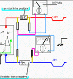
If you want to know how to measure the stand by current
Without the need to install series current meters.
Install resistance, low value, in series with the positive and negative rail. The current will cross the resistance and a voltage will appear over those resistor extremes.... so, you will read DC voltage and them divide this voltage readed by the resistance you have installed.
The image is a copy of a brazilian forum instructions.... in the example shown...you have 0,5 Volts....and 5 ohms..... the division result is 0.1A (100 miliamperes).
This is the way to measure both rail currents...and also to protect circuit if something is wrong there....because the resistor will limit the current to a value that will be your supply voltage divided by 5 (5 ohms)
This is used to adjust stand by current..without any signal in the input.... if you create a short circuit in the amplifier's input...will be better.
After adjustment, remember to remove those resistors and to install a fuse in its place....to your schematic....use 6 amperes if you intend to install 4 ohms speakers....and 3 amperes if the speaker to be installed has 8 ohms impedance.
A 6 amps fuse to protect the speakers...in series with the output line, will be good too.
regards,
Carlos
Attachments
hi everyone,
thanks for advice, i am on it, thats realy easy
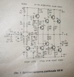
Wavebour, its from czechoslovakian diy magazine "Amaterske Radio" this one is from 1984
so far i am not using any fuses, the power supply is temporary
Tube_Dude, i am not going to rebuilt the output stage, at this point it is using matched transistors for which it was designed
i just plan to finish it and test its sound in comparison to other amps
and i will definitely replace that cap
Zen Mod, thanks, i will adjust the current in output transistors most likely above 50 mA, and than i will experiment with sound, once i finish power supply
what is your preference when it comes to the sound? what could sound better, higher current? i guess it matters what it was designed for
anyway, thanks for your help, it has very promissing sound adn i will finish it
ed
thanks for advice, i am on it, thats realy easy
Wavebour, its from czechoslovakian diy magazine "Amaterske Radio" this one is from 1984
so far i am not using any fuses, the power supply is temporary
Tube_Dude, i am not going to rebuilt the output stage, at this point it is using matched transistors for which it was designed
i just plan to finish it and test its sound in comparison to other amps
and i will definitely replace that cap
Zen Mod, thanks, i will adjust the current in output transistors most likely above 50 mA, and than i will experiment with sound, once i finish power supply
what is your preference when it comes to the sound? what could sound better, higher current? i guess it matters what it was designed for
anyway, thanks for your help, it has very promissing sound adn i will finish it
ed
adason said:
Zen Mod, thanks, i will adjust the current in output transistors most likely above 50 mA, and than i will experiment with sound, once i finish power supply
what is your preference when it comes to the sound? what could sound better, higher current? i guess it matters what it was designed for
ed
whatever amount of current pleases you and your ears
looking at those heatsinks, I wouldn't try more than 15W dissipation per channel.....meaning that you can't put more than 200mA.....but also no less than 100mA,as wavebourn told ya ( my eyes skipped that part -small value of R21 and R22)
anyway-replace that crappy Tesla elco (C3 ? ) immediately,along with both trimpots- I know them more than well
I wish ya nice building and listening .....
EDIT:
yes-I prefere higher currents

Wavebourn said:I think about 150-200 mA will be enough for this amp (about 100 mA is needed for pre-driver transistors).
How? ... The pre-drivers T6/7 work with 1,5 mA and the drivers T8/9 work with 12 mA ..I can't see where your 100 mA for the drivers come from...
Tube_Dude said:
How? ... The pre-drivers T6/7 work with 1,5 mA and the drivers T8/9 work with 12 mA ..I can't see where your 100 mA for the drivers come from...
My typo, I meant a driver. If output followers are biased (I would rather not, or bias for a heavy current), your driver transistors will consume 500mV/5Ohm=100MA roughly. If to bias T8/9 on 12 mA you screw down the whole idea and turn the amp into a standard s***t.
Wavebourn said:Oops... Sorry again, it is a standard amp - looks like resistors are 47 Ohm, not 4.7 Ohm as I thought before...
same mistake I made .......nah-47,not 4E7
gentlemen,
i never said the amp is something special
as a matter of fact, i indicated it was an old schematics
nevertheless, so far it sounds clean, very clean
i did not plug it to Lowthers, and i do not intend to, just some small coaxial speakers, but i will compare it with other amps, once finished, on my second system
besides, i am working on line array speakers right now which means i will need another amp
otherwise thanks for good advice, i will set the current based on listening
ed
- Status
- This old topic is closed. If you want to reopen this topic, contact a moderator using the "Report Post" button.
- Home
- Amplifiers
- Solid State
- old commies amp working, few questions