Re: not exactly on topic - but predistortion could be error correction too
Any info on the linearization algorithms they're using? I'm only finding marketing blurbs on this site.
Too bad that the SHARC DSP doing oversampling in the DAC I'm working on likely won't have enough spare cycles for this though :/
Any info on the linearization algorithms they're using? I'm only finding marketing blurbs on this site.
Too bad that the SHARC DSP doing oversampling in the DAC I'm working on likely won't have enough spare cycles for this though :/
Look here:
Curing Nonlinear Distortion
While the idea is appealing, it looks like a real challenge to get that working for a power amplifier, because distortion is IMHO non-static, a function of (at least) three quite uncorrelated variables, in order of influence
- output current
- output voltage
- time (thermal/power influences, the "memory aspect")
Maybe our children will eventually see a system that measures and adapts itself on the fly... OTOH, by then there might only exist matured class-D amp designs which won't need all that correction stuff...
- Klaus
Bob, what happened to your third valid view? You say it is equally as valid as the others.
valid viewsThe third view of HEC is the “low feedback” view. Here it is recognized that the emitter follower output stage needs a little bit of a gain boost to get its gain back to exactly unity. This can only be accomplished with a very slight bit of net positive feedback. 1/(1-AB) factor will have to come out to about 1.053 in this case. The amount of slight positive feedback is arrived at by what amounts to a bridge circuit, where a subtraction takes place between what is put into the output stage and what comes out of the output stage. This creates a very small residual amount of feedback that has a very small amount of loop gain that can be positive or negative feedback. In this case, it will usually be slightly positive as mentioned above.
The magic in this view of HEC is that the feedback factor is adaptive in that the error in the output stage adapts, or adjust the small amount of feedback needed to correct the incremental gain of the stage. The key here is to realize that the actual amount of correction that needs to be applied to the emitter follower output stage is quite small, so that only a very small amount of net feedback is necessary.
The important point is that all three of these ways of looking at HEC are valid. Each offers its own insights, and each has its limitations in what it reveals. The error correction view can be very intuitive for some, but it does not excel at revealing stability issues. The negative feedback view is probably better at revealing stability issues in a traditional feedback analysis sense, but it can be confusing to some because of its implied positive feedback and infinite gain.
Cheers,
Bob
Re: not exactly on topic - but predistortion could be error correction too
Definitely, this is what we are (hopefully) going to see.
As for real implementations, my hunch is a neural network architecture where the predistortion engine will "learn" with suitable test signals how to converge to a solution taking into account the particular amplifier, load, environment and so forth.
Rodolfo
jcx said:........
enough dsp horsepower could run a good model w/online identification and multiple measured inputs - Vds,gs, Is, Vps, case,heatsink temps and calculate a predistortion V for the output stage of audio amps too
Definitely, this is what we are (hopefully) going to see.
As for real implementations, my hunch is a neural network architecture where the predistortion engine will "learn" with suitable test signals how to converge to a solution taking into account the particular amplifier, load, environment and so forth.
Rodolfo
But that's exactly what those devices claim to do, and at even much higher frequencies.KSTR said:While the idea is appealing, it looks like a real challenge to get that working for a power amplifier
Even the article you noted discusses cases with memory and doesn't restrict the approach to static errors. There seem to be also a few papers floating around where machine learning is applied, such as genetic algorithms in this one:- time (thermal/power influences, the "memory aspect")
http://etd.gatech.edu/theses/availa...3/unrestricted/sperlich_roland_200508_phd.pdf
A simpler approach is US patent 7,149,257.
If RF systems can do it now, why can't audio?Maybe our children will eventually see a system that measures and adapts itself on the fly
KSTR said:....... OTOH, by then there might only exist matured class-D amp designs which won't need all that correction stuff...
...
Class D amplifiers need correction too, there are non ideal switching times and power rail fluctuations just to begin with.
Rodolfo
Re: Re: Re: Re: Re: Re: hec != hoax ?
Hello Bob,
Thanks for your recap, which I have compressed (very!) in order to save bandwidth.
As you noted, the final result, although obtained with different topologies, may well be equivalent in a practical realisation.
Referring to your first view of HEC, the high gain block to allow the nfb to do its work, is not generated by a high-gain (forward) amplifier stage but rather by the positive feedback loop. That means that the forward amplifier path can be a bit simpler, and can be limited in ol gain to the required nominal cl gain. It may not always give an advantage in complexity as there is now increased complexity in the feedback circuitry, but that is not what I want to address.
Ever since Otala (and even before) we have been aware of internal amplifier overshoot, slew rate limiting etc, phenomena that are generally ascribed to high internal (ol) gain. So I wonder if one of the so far not mentioned advantages of HEC, with a low ol gain forward path, might be a (much) lesser susceptibility to these issues. I know that these issues can be adequately taken care of in a 'classical' nfb amp; I'm just trying to find if there are possible differences in this regard that have not yet be mentioned.
For example, the case of clipping. Suppose that Vout falls 5V short of the undistorted output due to clipping. With a classical feedback factor of 20, that means an additional 0.25V input signal to an amp that perhaps has 70dB open loop gain, so we need to be carefull to handle this overdrive.
In the cas of HEC with say an ol gain of 20 and a nfb factor also 20, we would have the same additional 0.25 input voltage from the nfb loop, but now our ol gain is only 20 so I would expect the overdrive etc to be a lesser issue.
[Afterthought: The above is not limited to unity-gain output stages of course but specifically in cases where the required gain is higher].
[Second Afterthought: There is a clear relation between Vin and Vout in the 2nd view, via the low ol gain. So, at first sight, with the same effective Vin, overload should be a lesser problem. BUT, we have this positive feedback loop, so in this case possibly the effective Vin is actually higher than in the classic nfb loop case. But I'm not clear on that.]
I would appreciate your views on this.
Jan Didden
Bob Cordell said:The two views of HEC are both valid and both are useful.
[snip]Cheers,
Bob
Hello Bob,
Thanks for your recap, which I have compressed (very!) in order to save bandwidth.
As you noted, the final result, although obtained with different topologies, may well be equivalent in a practical realisation.
Referring to your first view of HEC, the high gain block to allow the nfb to do its work, is not generated by a high-gain (forward) amplifier stage but rather by the positive feedback loop. That means that the forward amplifier path can be a bit simpler, and can be limited in ol gain to the required nominal cl gain. It may not always give an advantage in complexity as there is now increased complexity in the feedback circuitry, but that is not what I want to address.
Ever since Otala (and even before) we have been aware of internal amplifier overshoot, slew rate limiting etc, phenomena that are generally ascribed to high internal (ol) gain. So I wonder if one of the so far not mentioned advantages of HEC, with a low ol gain forward path, might be a (much) lesser susceptibility to these issues. I know that these issues can be adequately taken care of in a 'classical' nfb amp; I'm just trying to find if there are possible differences in this regard that have not yet be mentioned.
For example, the case of clipping. Suppose that Vout falls 5V short of the undistorted output due to clipping. With a classical feedback factor of 20, that means an additional 0.25V input signal to an amp that perhaps has 70dB open loop gain, so we need to be carefull to handle this overdrive.
In the cas of HEC with say an ol gain of 20 and a nfb factor also 20, we would have the same additional 0.25 input voltage from the nfb loop, but now our ol gain is only 20 so I would expect the overdrive etc to be a lesser issue.
[Afterthought: The above is not limited to unity-gain output stages of course but specifically in cases where the required gain is higher].
[Second Afterthought: There is a clear relation between Vin and Vout in the 2nd view, via the low ol gain. So, at first sight, with the same effective Vin, overload should be a lesser problem. BUT, we have this positive feedback loop, so in this case possibly the effective Vin is actually higher than in the classic nfb loop case. But I'm not clear on that.]
I would appreciate your views on this.
Jan Didden
Re: Re: not exactly on topic - but predistortion could be error correction too
For this problem maybe something like a non-linear conjugate gradient method would be simpler and more efficient.ingrast said:As for real implementations, my hunch is a neural network architecture where the predistortion engine will "learn" with suitable test signals how to converge to a solution taking into account the particular amplifier, load, environment and so forth.
Re: Re: Re: not exactly on topic - but predistortion could be error correction too
Interesting, could you post a link for reference?
Rodolfo
abzug said:
For this problem maybe something like a non-linear conjugate gradient method would be simpler and more efficient.
Interesting, could you post a link for reference?
Rodolfo
jcx wrote:

Jcx, I don't think this is off-topic at all. It concerns techniques for deriving the input signal to the non-linear plant that is necessary to cause the output to be linear. That paper Klaus posted is very interesting and illustrates how pre-distortion cannot be derived using a simple linear network. Sometimes it cannot be derived at all.
I knew a colleague who designed pre-distortion processors for mobile phones. I was very interested in applying it to audio but on investigation the speed of the correction was too slow. The rate of change of distortion is much slower in a mobile device. I concur with Klaus that the dynamic nature of audio amp distortion will certainly reduce the effectiveness of a pre-distorter. Every little linearisation counts, though.
Has anyone had experience with adaptive pre-distortion?
On-board Spice co-processor?enough dsp horsepower could run a good model w/online identification and multiple measured inputs - Vds,gs, Is, Vps, case,heatsink temps and calculate a predistortion V for the output stage of audio amps too
Jcx, I don't think this is off-topic at all. It concerns techniques for deriving the input signal to the non-linear plant that is necessary to cause the output to be linear. That paper Klaus posted is very interesting and illustrates how pre-distortion cannot be derived using a simple linear network. Sometimes it cannot be derived at all.
I knew a colleague who designed pre-distortion processors for mobile phones. I was very interested in applying it to audio but on investigation the speed of the correction was too slow. The rate of change of distortion is much slower in a mobile device. I concur with Klaus that the dynamic nature of audio amp distortion will certainly reduce the effectiveness of a pre-distorter. Every little linearisation counts, though.
Has anyone had experience with adaptive pre-distortion?
KSTR said:Si, Rodolfo, por eso escrib�a "matured designs"....
Saludos, Klaus
True, what I meant was those mature designs will most probably include some form of correction.
Sorry I cannot return the courtesy in german

Rodolfo
traderbam said:Bob, what happened to your third valid view? You say it is equally as valid as the others.
valid views
Edmond was just asking about the two views, and I did not want to add confusion. The third is valid and interesting, but is not as appealing to me as the other two. It was originally listed for completeness.
Bob
Re: Re: Re: Re: Re: Re: hec != hoax ?
Hi Bob,
Thank you for your perfect expose, well, almost perfect.
Starting with the EC view of HEC, you wrote:
but there are caveats. Stability of the arrangement must be maintained
Why? How do you know this? The EC view didn't tell you this.
You only can know this by surreptitiously looking at the NFB approach.
Happily, you have corrected yourself later on by asserting that:
The negative feedback view is better at revealing stability issues")
In the mean time I've tweaked my amp a little bit and the results are coming soon.
Cheers, Edmond.
Hi Bob,
Thank you for your perfect expose, well, almost perfect.
Starting with the EC view of HEC, you wrote:
but there are caveats. Stability of the arrangement must be maintained
Why? How do you know this? The EC view didn't tell you this.
You only can know this by surreptitiously looking at the NFB approach.
Happily, you have corrected yourself later on by asserting that:
The negative feedback view is better at revealing stability issues
In the mean time I've tweaked my amp a little bit and the results are coming soon.
Cheers, Edmond.
Bob, do you still consider this statement a valid view?
"A MOSFET Power Amplifer with Error Correction", Cordell, JAES, Vol 32 1984Note that this is an error-cancellation technique like feedforward as opposed to an error-reduction technique like negative feedback. This technique is in a sense like the dual of feedforward.
Re: Re: Re: Re: Re: Re: Re: hec != hoax ?
Hi Edmond, thanks.
Even in my original MOSFET amplifier paper, I stated in the fourth paragraph of Section 2.2, "The technique of Figure 11 [HEC block diagram] also tends to become less effective at very high frequencies because, being a feedback loop (albeit not a traditional negative feedback loop), it requires some amount of compensation for stability, detractinmg from the phase and amplitude matching." In the sixth paragraph of that section I specifically mention the frequency compensation and the components involved.
Although it is hard to remember what was in one's mind 25 years ago, I don't think there was ever a point in time when I did not realize that some form of frequency compensation was needed in HEC.
Cheers,
Bob
Edmond Stuart said:Hi Bob,
Thank you for your perfect expose, well, almost perfect.
Starting with the EC view of HEC, you wrote:
but there are caveats. Stability of the arrangement must be maintained
Why? How do you know this? The EC view didn't tell you this.
You only can know this by surreptitiously looking at the NFB approach.
Happily, you have corrected yourself later on by asserting that:
The negative feedback view is better at revealing stability issues
In the mean time I've tweaked my amp a little bit and the results are coming soon.
Cheers, Edmond.
Hi Edmond, thanks.
Even in my original MOSFET amplifier paper, I stated in the fourth paragraph of Section 2.2, "The technique of Figure 11 [HEC block diagram] also tends to become less effective at very high frequencies because, being a feedback loop (albeit not a traditional negative feedback loop), it requires some amount of compensation for stability, detractinmg from the phase and amplitude matching." In the sixth paragraph of that section I specifically mention the frequency compensation and the components involved.
Although it is hard to remember what was in one's mind 25 years ago, I don't think there was ever a point in time when I did not realize that some form of frequency compensation was needed in HEC.
Cheers,
Bob
Re: Re: Re: Re: Re: Re: Re: hec != hoax ?
Hi Jan,
These are interesting questions. I can't say that I have a strong view on them. One thing that I think is a useful observation (but which is an advanatge shared by Edmond's approach as well) is that the HEC technique furthers the philosophy of making each stage as locally linear as possible before applying global feedback.
Local, tight, fast loops can do a better job in many cases than the global loop. I have always believed that one of the benefits of HEC, whether you view it as error correction or as NFB with a high forward gain realized by PFB, is that it is a fast, tight, local loop around the output stage. Speed is King, and the HEC architecture lends itself to high speed.
Conventional amplifiers suffer because the linearization of the worst offender, the output stage, is largely left to only the global feedback loop.
Cheers,
Bob
janneman said:
Hello Bob,
Thanks for your recap, which I have compressed (very!) in order to save bandwidth.
As you noted, the final result, although obtained with different topologies, may well be equivalent in a practical realisation.
Referring to your first view of HEC, the high gain block to allow the nfb to do its work, is not generated by a high-gain (forward) amplifier stage but rather by the positive feedback loop. That means that the forward amplifier path can be a bit simpler, and can be limited in ol gain to the required nominal cl gain. It may not always give an advantage in complexity as there is now increased complexity in the feedback circuitry, but that is not what I want to address.
Ever since Otala (and even before) we have been aware of internal amplifier overshoot, slew rate limiting etc, phenomena that are generally ascribed to high internal (ol) gain. So I wonder if one of the so far not mentioned advantages of HEC, with a low ol gain forward path, might be a (much) lesser susceptibility to these issues. I know that these issues can be adequately taken care of in a 'classical' nfb amp; I'm just trying to find if there are possible differences in this regard that have not yet be mentioned.
For example, the case of clipping. Suppose that Vout falls 5V short of the undistorted output due to clipping. With a classical feedback factor of 20, that means an additional 0.25V input signal to an amp that perhaps has 70dB open loop gain, so we need to be carefull to handle this overdrive.
In the cas of HEC with say an ol gain of 20 and a nfb factor also 20, we would have the same additional 0.25 input voltage from the nfb loop, but now our ol gain is only 20 so I would expect the overdrive etc to be a lesser issue.
[Afterthought: The above is not limited to unity-gain output stages of course but specifically in cases where the required gain is higher].
[Second Afterthought: There is a clear relation between Vin and Vout in the 2nd view, via the low ol gain. So, at first sight, with the same effective Vin, overload should be a lesser problem. BUT, we have this positive feedback loop, so in this case possibly the effective Vin is actually higher than in the classic nfb loop case. But I'm not clear on that.]
I would appreciate your views on this.
Jan Didden
Hi Jan,
These are interesting questions. I can't say that I have a strong view on them. One thing that I think is a useful observation (but which is an advanatge shared by Edmond's approach as well) is that the HEC technique furthers the philosophy of making each stage as locally linear as possible before applying global feedback.
Local, tight, fast loops can do a better job in many cases than the global loop. I have always believed that one of the benefits of HEC, whether you view it as error correction or as NFB with a high forward gain realized by PFB, is that it is a fast, tight, local loop around the output stage. Speed is King, and the HEC architecture lends itself to high speed.
Conventional amplifiers suffer because the linearization of the worst offender, the output stage, is largely left to only the global feedback loop.
Cheers,
Bob
PMA said:Unfortunately, these threads lost any information value.
Hi PMA,
I agree that the level of information value comes and goes, but I urge you to be patient. It is also unfortunately true that semantical controversies sometimes interfere with the more productive aspects of the discussion. I think that Edmond's contributions regarding non-HEC ways of improving output stage performance have actually re-vitalized the discussion.
Cheers,
Bob
Non-HEC-amp
Hi Bob,
Is it really that hard to get my point? It doesn't matter what you know, the point is what the EC point of view (without any knowledge of other points of view and practical experience) has to offer. Never mind, so let's go to business.
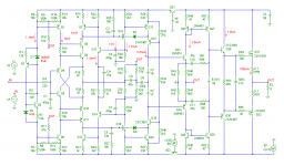
Here's the simplified schematic of my amp with the NFB output stage. As you can see, the input stage as well as the output stage utilizes current feedback and the bias of the symmetrical VAS is stabilized by a common mode control loop (Q7,12,13,14)
Just as in your design, the 'Miller' compensation is applied between the VAS output and the inverting input of the IPS.
Despite the fact that a CFB IPS is faster than a LTP, also in this design it was necessary to add one more pole and zero (C3,R26, resp. C5,R27) to get the front-end stable.
As we all know, the Early effect isn't accurately modeled by most simulators. So, to be on the safe side, I've eliminated this effect completely by bootstrapping (R10,11,etc,) and by using CF cascodes (Q8,11,18,19), Maybe it's superfluous. OTOH, the added cost is virtual nihil. BTW, the THD20 of the front-end with this arrangement is only 10ppb.
The TMC network consists of C9, R35 and R35.
And here are some key figures, where Fc is the unity gain frequency of a loop, PM the phase margin and GM the gain margin.
Output stage: Fc = 2.9MHz, PM = 76 deg., GM = 26dB
Global FB loop: Fc = 900kHz, PM = 87 deg., GM = 21dB
Miller loop: Fc = 9MHz, PM = 73 deg., GM = 6dB
CMCL: Fc = 350kHz, PM = 64 deg., GM = 45 dB
TMC: Fc = 1MHz.
Slew rate: 200V/us.
THD20 at 50W: 0.65ppm, at 100W: 0.9ppm (into 8 Ohm, BW=100kHz)
In the next posts I'll show the distortion spectra and the (slightly) improved step response.
Cheers, Edmond.
Bob Cordell said:Hi Edmond, thanks.
Even in my original MOSFET amplifier paper, I stated in the fourth paragraph of Section 2.2, "The technique of Figure 11 [HEC block diagram] also tends to become less effective at very high frequencies because, being a feedback loop (albeit not a traditional negative feedback loop), it requires some amount of compensation for stability, detractinmg from the phase and amplitude matching." In the sixth paragraph of that section I specifically mention the frequency compensation and the components involved.
Although it is hard to remember what was in one's mind 25 years ago, I don't think there was ever a point in time when I did not realize that some form of frequency compensation was needed in HEC.
Cheers,
Bob
Hi Bob,
Is it really that hard to get my point? It doesn't matter what you know, the point is what the EC point of view (without any knowledge of other points of view and practical experience) has to offer. Never mind, so let's go to business.
Here's the simplified schematic of my amp with the NFB output stage. As you can see, the input stage as well as the output stage utilizes current feedback and the bias of the symmetrical VAS is stabilized by a common mode control loop (Q7,12,13,14)
Just as in your design, the 'Miller' compensation is applied between the VAS output and the inverting input of the IPS.
Despite the fact that a CFB IPS is faster than a LTP, also in this design it was necessary to add one more pole and zero (C3,R26, resp. C5,R27) to get the front-end stable.
As we all know, the Early effect isn't accurately modeled by most simulators. So, to be on the safe side, I've eliminated this effect completely by bootstrapping (R10,11,etc,) and by using CF cascodes (Q8,11,18,19), Maybe it's superfluous. OTOH, the added cost is virtual nihil. BTW, the THD20 of the front-end with this arrangement is only 10ppb.
The TMC network consists of C9, R35 and R35.
And here are some key figures, where Fc is the unity gain frequency of a loop, PM the phase margin and GM the gain margin.
Output stage: Fc = 2.9MHz, PM = 76 deg., GM = 26dB
Global FB loop: Fc = 900kHz, PM = 87 deg., GM = 21dB
Miller loop: Fc = 9MHz, PM = 73 deg., GM = 6dB
CMCL: Fc = 350kHz, PM = 64 deg., GM = 45 dB
TMC: Fc = 1MHz.
Slew rate: 200V/us.
THD20 at 50W: 0.65ppm, at 100W: 0.9ppm (into 8 Ohm, BW=100kHz)
In the next posts I'll show the distortion spectra and the (slightly) improved step response.
Cheers, Edmond.
Attachments
- Home
- Amplifiers
- Solid State
- Bob Cordell Interview: Error Correction