This one is from here
http://www.diyaudio.com/forums/showthread.php?postid=1141588#post1141588
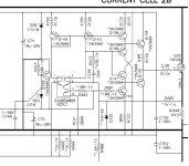
Q1+Q2+D1+D2 seems to form correction loop
http://www.diyaudio.com/forums/showthread.php?postid=1141588#post1141588
Q1+Q2+D1+D2 seems to form correction loop
Attachments
lumanauw said:This one is from here
http://www.diyaudio.com/forums/showthread.php?postid=1141588#post1141588
Q1+Q2+D1+D2 seems to form correction loop
Those devices form an interesting negative feedback loop. Matching among the diodes and the transistors is an issue for this interesting circuit.
Bob
lumanauw said:This one is from here
http://www.diyaudio.com/forums/showthread.php?postid=1141588#post1141588
Q1+Q2+D1+D2 seems to form correction loop
The output stage works in fact as a regular negative feedback loop, being the noninverting input at Q1-Q2 emitter junction and D1-D2 junction (output) the inverting input.
An interesting feature is the potentially large bandwidth (non inverting) resulting from Q1/Q2 working common base. Probably this circuit could benefit from an additional overall negative feedback loop, setting the inner OpAmp feedback so as to have a moderately high gain (10 - 100 times amplifier set gain).
Drawbacks are low output stage input impedance toghether with unity gain, which places severe drive requirements for the OpAmp.
As Bob noted, matching of D1-D2 V/I curve with Q1-Q2 Vbe/Ie curve may be tricky.
---Correction--- There is no possible match since Q1-Q2 Ie is basically constant while D1-D2 see the load current.
Rodolfo
This looks like a mini-CFA follower inside the overall op-amp loop. Those 1.5mA currents end up driving the MOSFET capacitances in one direction or other, could be a problem as a general purpose technique (ie. if the FETs have 1000pF of Cgs).
EDIT - Sorry just noticed the loop isn't closed around the whole thing - still have to slew those MOSFET gates.
EDIT - Sorry just noticed the loop isn't closed around the whole thing - still have to slew those MOSFET gates.
mikeks said:An interesting take on EC
I fail to see the interesting crumb, it looks like a 3d semester engineering school textbook on controll systems.
Must be me: too early, the coffee meter doesn't read 50% yet.
mikeks said:
Hi Mike,
It would be even more interesting if I could read Japanese!
Can you tell what the point is that he is trying to make?
Thanks,
Bob
Bob Cordell said:
Hi Mike,
It would be even more interesting if I could read Japanese!
Can you tell what the point is that he is trying to make?
Thanks,
Bob
Yes, Japanese would be good, but is not necessary for a fundamental appreciation of his points, some of which are rather misleading.
In essence he attempts to cover issues beaten to death, here, here and here, but in a much less intuitive fashion.
powerbecker said:I use only inverting amps for the summers, because they have for this purpose the smallest error...as models ..and in reality!
Heinz!
Heinz,
The inverting summers you've used here are not a good idea because U1 has to swing roughly twice the output voltage, making it the predominant source of intra-loop non-linearity.
mikeks said:Yes, but a gain other than unity reduces loop gain local to each op amp. Result? More distortion.
Solution? Use diff amps, or diff amp+summing inverter.
Please demonstrate it, and dont´t forget to simulate the diff amp with realistic values and tolerances!
mikeks said:Nothing to do with EC.
Thats why I mentioned Transconductance! not EC
I am trying to find a schematic for a amp with error correction but with 4 pairs of output mosfets. I have plenty of spare laterals here.
I think there was a design from Tandberg that used error correction (european amp I think). Something like 8009A, 9008A ?? Think it was printed in Electronics and Wireless World.
I could just add more outputs to an existing design but it may go bang!. The loop stability of the EC output stage may be a problem.
- Home
- Amplifiers
- Solid State
- Bob Cordell Interview: Error Correction