Re: Re: Superbly intuitive analysis!
It does not depend on is the output stage under-biased, or is not. The point is, no matter how linear is the current cunsumption by output stage from driver, if it is less than idle current through the driver, it is in A class. It is just a definition of A class, more semantic matter than electronic.
mikeks said:
Actually, i have now found this not to be entirely true:
Whether Q7/Q8 operate in Class A is also a function of the size of the cross-coupling resistor, the magnitude of the load and is dependent on the entire output stage not being under-biased.
This, to a much lesser extent, is also true of the first pair of cross-coupled drivers in Locanthi's arrangement.
It does not depend on is the output stage under-biased, or is not. The point is, no matter how linear is the current cunsumption by output stage from driver, if it is less than idle current through the driver, it is in A class. It is just a definition of A class, more semantic matter than electronic.
You don't really believe any part of the output stage will operate in class A with zero bias, do you?
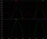
Proof below:
Bias=1V (underbiased by ~1.7V)
Driving 2ohms.
Green Trace: Q5 collector current.
Red Trace: Q7 collector current.
Blue Trace: Q5 collector current (Locanthi).
Sky Blue Trace: Q7 collector current (Locanthi).
Notice that all the drivers here, regardless of cross-coupling or lack thereof, are now operating in Class B or AB.
Attachments
Re: Re: Re: Superbly intuitive analysis!
It would perhaps be better to ascertain the definition of ''push-pull Class A'' before committing oneself; this information is readily available on the Web.
Wavebourn said:It is just a definition of A class, more semantic matter than electronic.
It would perhaps be better to ascertain the definition of ''push-pull Class A'' before committing oneself; this information is readily available on the Web.
MikeB said:
Why not, as amount of feedback reduces, compensation reduces ?
And as openloop gain reduces, feedback reduces, right ?
And unlinearity changes gain with level, right ?
Compensation remains constant, unless you've invented a new class of passive devices whose values vary significantly and linearly with frequency.
Yes, loop gain reduces as forward path gain reduces, since the former is a function of the later.
I am afraid i haven't quite understood your last sentence.
mikeks said:
I am afraid i haven't quite understood your last sentence.
Hmm, this was the most important... (I am not good at explaining)
As unlinearity represents a transfer curve, the gain of the distorting stage/device is level dependent.
Imagine a simple quadratic transfer curve, a signal offsetted at nearly the bottom of this curve gets less gain than a signal having its offset at nearly the top of the same curve.
Because of this, these 2 signals will receive different amounts of feedback. That's how a low freq at large scale will modulate the amount of feedback of an superimposed higher freq at smaller scale.
Mike
THD Analyzer Construction Article
Hi Tony,
In regard to your question about my THD Analyzer article published back in the '80's in Audio, the full construction article now appears as a PDF on my site at www.cordellaudio.com.
The analyzer was never offered as a kit, per se, but PWBs were offered at the time. As far as I know, they are no longer available. Of course, the artwork for them is in the Audio article.
The analyzer is still working great, and in fact I used it in the Amplifier Measurements Workshop at RMAF.
Technology has come a long way since then. The rather large multi-gang selector switches used in the original design were expensive and time-consuming to wire. At a minimum, a new design would somehow dispense with those switches, possibly usung solid state switches or tiny relays on a pwb for the function.
It is very tempting to update the design because I do understand that there are many designers out there who could really use a good analyzer but don't have the money to plunk down on an Audio Precision instrument. Let's face it, that's the main reason I designed it in the first place for myself!
Maybe one of these days a construction article on an updated version of the analyzer will appear.
Thanks for your interest.
Bob
Re: Re: Homework...
True.
Wavebourn said:
If current through this resistor is more than peak current consumed by output stage from driver, the driver works in class A; otherwise it works in class AB .
True.
Re: THD Analyzer Construction Article
Excellent idea!
Bob Cordell said:
It is very tempting to update the design because I do understand that there are many designers out there who could really use a good analyzer but don't have the money to plunk down on an Audio Precision instrument. Let's face it, that's the main reason I designed it in the first place for myself!
Maybe one of these days a construction article on an updated version of the analyzer will appear.
Excellent idea!
Re: Re: Re: Re: Superbly intuitive analysis!
There are tooooo many opinions available from the Web.
Can you explein me please what is a sinle ended class B amp?
mikeks said:
It would perhaps be better to ascertain the definition of ''push-pull Class A'' before committing oneself; this information is readily available on the Web.
There are tooooo many opinions available from the Web.
Can you explein me please what is a sinle ended class B amp?
Phase Intermodulation and FM distortion
Just as the gain through an amplifier can be a function of signal level, so can the phase (or the delay). This is a well-known concern, especially in video amplifier design. This phenomenon can occur in amplifiers with or without negative feedback.
As mentioned in an earlier post, one can think of a large low frequency signal, like 50 Hz, modulating the small-sigal gain in the forward path of an amplifier, thus causing a smaller 10 kHz signal to see varying forward path gain. This, in turn, in a feedback amplifier, can cause the gain crossover frequency to increase and decrease with the low frequency signal excursion. This is essentially the closed loop bandwidth of the amplifier. This can cause a very small variation in phase shift through the amplifier.
Imagine an amplifier whose forward gain is varying by 1 percent with the low-frequency excursion. Assume also that the amplifier has 20 dB of negative feedback and a closed loop bandwidth of 200 kHz. The -3 dB frequency will thus vary from about 199 kHz to 201 kHz with the low frequency excursion. This very slightly varying pole frequency a decade above the highest portion of the audio band will cause a varying phase shift or time delay, but the amount will be very very small. This is phase intermodulation distortion (PIM).
However, there are also other sources of PIM. For example, the collector-base capacitance of a simple VAS stage, effectively in parallel with the Miller compensation capacitor, can modulate the feedback compensation value, once again causing the gain crossover frequency, and thus the closed loop bandwidth, to move around a very small amount as a function of the low-frequency excursion.
Take a look at the PIM paper on my site at www.cordellaudio.com for more discussion of this and for PIM measurements on a real amplifier.
Finally, keep in mind that PIM is the same thing as f.m. distortion, since phase is just the integral of frequency.
Bob Cordell
Re: Phase Intermodulation and FM distortion
Hi Bob, my concern was, as the forward gain of the amplifier modulates with the large low freq, the amount of feedback applied also modulates. As most amps using large miller cap already have 90° phasehift at 10khz (openloop), the resulting closed loop phasehift also modulates in respect to the modulated feedback.
As many "badly" designed amps easily reach OL-distortion far above 1%, the phase modulation for the 10khz signal might get quite severe, reaching levels above 1°, >300ns. (i'm not too good in math)
Am i hunting a phantom, or is this real ?
Mike
Bob Cordell said:
Imagine an amplifier whose forward gain is varying by 1 percent with the low-frequency excursion. Assume also that the amplifier has 20 dB of negative feedback and a closed loop bandwidth of 200 kHz. The -3 dB frequency will thus vary from about 199 kHz to 201 kHz with the low frequency excursion. This very slightly varying pole frequency a decade above the highest portion of the audio band will cause a varying phase shift or time delay, but the amount will be very very small. This is phase intermodulation distortion (PIM).
Hi Bob, my concern was, as the forward gain of the amplifier modulates with the large low freq, the amount of feedback applied also modulates. As most amps using large miller cap already have 90° phasehift at 10khz (openloop), the resulting closed loop phasehift also modulates in respect to the modulated feedback.
As many "badly" designed amps easily reach OL-distortion far above 1%, the phase modulation for the 10khz signal might get quite severe, reaching levels above 1°, >300ns. (i'm not too good in math)
Am i hunting a phantom, or is this real ?
Mike
Phase intermodulation
Mike,
Yes, we are saying the same thing: If open-loop gain gets modulated by a large signal, the amount of NFB will vary, and therefore the closed loop bandwidth will get modulated. The phenomenon is real, but we need to plug in the numbers and do the measurements to see how much it matters.
I built an instrument to do that about 25 years ago. It was a coherent IM analyzer. It first used a phase locked loop and synchronous (I) detector to synchronously "demodulate" the 6 kHz "carrier" of a SMPTE IM signal. This yielded a very high-sensitivity conventional SMPTE IM analyzer. I then added a second quadrature phase detector to synchronously demodulate the phase modulation on the 6 kHz carrier. The output of this "Q" demodulator was then calibrated in r.m.s. nanoseconds. I measured numerous op amps and a test power amplifier (the latter under different conditions of NFB). It was described in a paper given at an AES convention. The design description and data taken are on my web site at www.cordellaudio.com.
I have never heard of anyone else that built such a PIM analyzer, and have not seen anyone specify the PIM of their amplifiers.
Anyway, the PIM of the crappy old 741 op amp at gain of 10X at 6V rms into a 10K load was only about 3.9 ns. The PIM of a TL071 was about 1.6 ns.
The PIM of a 70-watt power amplifier of 1970 vintage and unsophisticated design was less than 10 ns at any level below clipping (it was about 6 ns at 50 watts). An experimental 35 watt power amplifier without negative feedback had PIM of about 50 ns to just below clipping. That same amplifier with NFB had PIM of about 10 ns to just below clipping. My MOSFET power amplifier with error correction had PIM of less than 0.1 ns (yes, 100 picoseconds).
Bob Cordell
A slightly different viewing angle:
The "spectral" structure of the PIM is very similar to the "normal" IMD. It means at measurement of the IMD by the conventional instrument we can't resolve between PIM and "normal" IMD, so that something like "total IMD" is measured. It seems to me the only practical reason to differ between PIM and non-P IM (besides the consequences for the theory and design) could be the eventual difference between perceptual mechanisms - and significance, indeed - of the distortions of both kinds. Is it an acceptable opinion ?
The "spectral" structure of the PIM is very similar to the "normal" IMD. It means at measurement of the IMD by the conventional instrument we can't resolve between PIM and "normal" IMD, so that something like "total IMD" is measured. It seems to me the only practical reason to differ between PIM and non-P IM (besides the consequences for the theory and design) could be the eventual difference between perceptual mechanisms - and significance, indeed - of the distortions of both kinds. Is it an acceptable opinion ?
Re: Homework...
Nope.
mikeks said:Perhaps folks would like to figure out whether the first pair of drivers in this output stage operates in Class A if the output devices are in Class B?
Nope.
Re: Phase intermodulation
A lot of work on this has been done in the context of ultraclean oscillators at the NIST, Boulder, Co and at other places:
Jan Li, E.S.Ferre-Pikal, F.L.Walls, D.Forbes, S.H.Talisa:
Predicting 1/f AM and PM noise in Si BJT Amplifiers - A new computer program
probable file name on NIST server: 1243.pdf
Fred L. Walls, Eva S.Ferre-Pikal, Steven R. Jefferts:
Origin of 1/f PM and AM Noise in Bipolar Junction Transistor Amplifiers
IEEE Transactions on Ultrasonics, Ferrorelectrics and frequency control
Vol44, No 2, March 97
1134.pdf
Delgado Aramburo, Ferre-Pikal, Walls, Ascarunz:
Comparision of 1/f PM noise in Commercial Amplifiers
1997 IEEE International Frequency Control Symposium
1207.pdf
(This sunday the NIST time frequency server seems to be down?)
They can measure the phase noise to below the thermal limit
using correlation techniques. The methods are not limited to 1/f
but 1/f is usually most troublesome.
1/f noise will matter in the audio range, especially for MOSFETS.
A HP5370 time intervall counter has a single shot period resolution of abt 25 ps
(often on ebay, and cheap because it does only 100 MHz.
The B version has more robust inputs).
Just filter away the high aggressor frequency and measure the period of the lower (victim) frequency.
Phase jitter in the low ns range should be easy to measure with a qualified scope that has a delayed time base.
Gerhard
Bob Cordell said:I have never heard of anyone else that built such a PIM analyzer, and have not seen anyone specify the PIM of their amplifiers.
Anyway, the PIM of the crappy old 741 op amp at gain of 10X at 6V rms into a 10K load was only about 3.9 ns. The PIM of a TL071 was about 1.6 ns.
The PIM of a 70-watt power amplifier of 1970 vintage and unsophisticated design was less than 10 ns at any level below clipping (it was about 6 ns at 50 watts). An experimental 35 watt power amplifier without negative feedback had PIM of about 50 ns to just below clipping. That same amplifier with NFB had PIM of about 10 ns to just below clipping. My MOSFET power amplifier with error correction had PIM of less than 0.1 ns (yes, 100 picoseconds).
A lot of work on this has been done in the context of ultraclean oscillators at the NIST, Boulder, Co and at other places:
Jan Li, E.S.Ferre-Pikal, F.L.Walls, D.Forbes, S.H.Talisa:
Predicting 1/f AM and PM noise in Si BJT Amplifiers - A new computer program
probable file name on NIST server: 1243.pdf
Fred L. Walls, Eva S.Ferre-Pikal, Steven R. Jefferts:
Origin of 1/f PM and AM Noise in Bipolar Junction Transistor Amplifiers
IEEE Transactions on Ultrasonics, Ferrorelectrics and frequency control
Vol44, No 2, March 97
1134.pdf
Delgado Aramburo, Ferre-Pikal, Walls, Ascarunz:
Comparision of 1/f PM noise in Commercial Amplifiers
1997 IEEE International Frequency Control Symposium
1207.pdf
(This sunday the NIST time frequency server seems to be down?)
They can measure the phase noise to below the thermal limit
using correlation techniques. The methods are not limited to 1/f
but 1/f is usually most troublesome.
1/f noise will matter in the audio range, especially for MOSFETS.
A HP5370 time intervall counter has a single shot period resolution of abt 25 ps
(often on ebay, and cheap because it does only 100 MHz.
The B version has more robust inputs).
Just filter away the high aggressor frequency and measure the period of the lower (victim) frequency.
Phase jitter in the low ns range should be easy to measure with a qualified scope that has a delayed time base.
Gerhard
MikeB said:Thanks Bob, 10ns does not sound much, it's questionable if that is audible... I'll investigate further...
44 KHz sample rate is abt 23 usec. or 23000 nsec.
The numeric output of an 16 or even 24 bit ADC
should be quite different if the input signal jitters 10 ns or
1/2300th of the sample period.
Gerhard

- Home
- Amplifiers
- Solid State
- Bob Cordell Interview: Error Correction