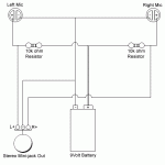
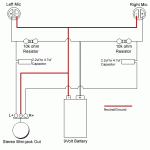
So using this site as a guide, http://webpages.charter.net/tidmarsh/binmic/ and more sepcifically this http://webpages.charter.net/tidmarsh/binmic/circuit.txt
I opened up photoshop and created (what I really hope to be) a stereo preamp circuit. My question, if it does turn out to be a preamp, would it work? Any changes you might suggest? and if it's not, are there any really simple ones out there that someone with basic soldering experience and lots of time could make? It's a little hard for me to understand curcuit diagrams as im still learning how to read them, but I think I did ok translating the one mentioned above into something I CAN understand
Please excuse my noobness
edit - this is for a binaural in-ear microphone btw
Attachments
This is not a preamp. It is a way to power a pair of condenser microphones. To make this work, you need to add capacitors in series with the left and right outputs. Connect the capacitors between the 10k resistors and the respective output connections to the jack. A good value would be 2.2uf to 4.7uf.
hi
10 kohm resistor may work well with some microphones
( actually will work with most any - nothing really bad will happen )
but there are a kind of electret condenser mics
that want these resistors to be 2200 ohm ( 2.2 kohm )
this is to get the best performance
At least this is the recommendation from the manufacturer, Panasonic.
I have got such microphone capsules myself
they are called:
Electret Condenser Microphones
Panasonic WM-61A, WM-61B, WM-034,
Read more about this and find some good links to Panasonic informations
in this topic 1 month ago:
diyAudio -> Everything Else -> Stereo binaural WM-61A with preamps
Here is the direct link to Panasonic Electret Condenser Microphones datasheets:
http://www.panasonic.com/industrial/components/audio/aud_mic.htm
regards
lineup
Prismatic said:This look alright?
Yes, If you are sure you should use 10 kohm
and not 2.2 kohm like I think is more suitable,
at least for some electret mics.
10 kohm = 10000 ohm
You have selected 10 ohm resistors!
My suggestion is try 2.2 kohm = 2200 ohm
Carbon resistors has got a bit more noise.
90% of all resistors we use for Audio HiFi are these
Metal Film !!!
Metal Film
A wide range of 1/4W Metal Film Resistors with 1% tolerance,
suitable for applications requiring tight tolerances.
Highly stable and low noise characteristics,
together with low temperature co-efficient
makes these resistors ideal for the most demanding applications.
http://www.futurlec.com/Resistors.shtml
--------------------------------
But avoid using Electrolytic Caps for input/output of audio signals.
You should use plastic film caps.
The best one, 2.2 uF that
http://www.futurlec.com/Capacitors.shtml
company has got
is this one, I think:
C2200UM 2.2uF 100V Mylar Capacitors
http://www.futurlec.com/Capacitors/C2200UMpr.shtml
2.2 uF Mylar 100 Volt will be much better than electrolyt 3.3 uF
Even better of course would be 3.3 or 4.7 uF Mylar, ( the higher value, the better )
but as they have only 2.2 uF of Mylar ....
You dont know any better and bigger internet company for electronic components in your region?
That has got a little bit more stuff to chose from and such capacitors
that are really suited for audio.
For best results ( 9 people of 10 at this forum would do this )
you should use Polypropylene capacitors
Have the highest quality for audio signals.
Cost a bit more, and comes in values 1.0 1.5 2.2 3.3 4.7 6.8 and 10 uF.
Sometimes even 22 uF and 47 uF, but those are real EXPENSIVE!
- Status
- This old topic is closed. If you want to reopen this topic, contact a moderator using the "Report Post" button.
- Home
- Amplifiers
- Solid State
- Not really sure if this would even work, preamp?


