Hello,
after playing around, building and modifing some circuits of the Alephs I know want to build an mic preamp without only copying a schemtic found on the web.
Here are some specifications of what I want:
- fully discrete design of main signal path
- class A output stage
- complete symmetric design (or similar to the double balanced design of Graham John Cohen)
- Gain: 0...+63dBu
- max output level: +27dBu
- max input level: +14dBu
- input impedance: switchable between 300, 600, 1200, and 2400 Ohms for optimal mic matching
- output impedance: 600Ohms
- no transformer
- 48V phantom voltage
These specifications should be sufficient for many applications and are taken from looking on many commercial produts.
Any hints and tips are welcome.
My first question is, starting with the input stage, which transistors should I use? At a first glance I would take the BC184C.
Greetings,
Raphael
Lineup Audio Lab - Emitter Microphone Amplifier
.
hi, AudioAngel
One of the many projects i am currently working with
is my
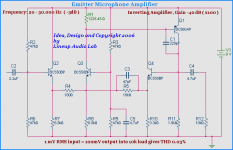
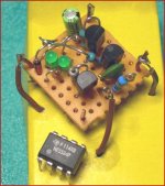
Emitter Microphone Amplifier.
Intended for 9 volt battery supply and to be placed CLOSE to electret mic capsule.
This way raise the signal ( 40dB ) and so stay clear from noise level in mic cable.
Inverting amplifier.
Supply current 4.98 mA at 9.0 Volt.
Gain -40 dB ( = x100 )
1 mV RMS in gives 100 mV RMS out, into 10 kohm load
at 0.03% THD total harmonic distortion
There are a few details to deal with and some real improvements to make
before this project is completed.
Like to solve what happens when battery goes down to 7-8 volts.
Goal is to make it work just as well as it does at 9.0 volt,
within the voltage span of 6.0 - 10.0 VDC.
This way it should be possible to power this unit
using both 9V alkaline but also rechargeable 7.2V cell.
Enjoy
My attachment schematic!
lineup
Lineup Audio Lab
http://lineup.awardspace.com/
.
hi, AudioAngel
One of the many projects i am currently working with
is my
Emitter Microphone Amplifier.
Intended for 9 volt battery supply and to be placed CLOSE to electret mic capsule.
This way raise the signal ( 40dB ) and so stay clear from noise level in mic cable.
Inverting amplifier.
Supply current 4.98 mA at 9.0 Volt.
Gain -40 dB ( = x100 )
1 mV RMS in gives 100 mV RMS out, into 10 kohm load
at 0.03% THD total harmonic distortion
There are a few details to deal with and some real improvements to make
before this project is completed.
Like to solve what happens when battery goes down to 7-8 volts.
Goal is to make it work just as well as it does at 9.0 volt,
within the voltage span of 6.0 - 10.0 VDC.
This way it should be possible to power this unit
using both 9V alkaline but also rechargeable 7.2V cell.
Enjoy
My attachment schematic!
lineup
Lineup Audio Lab
http://lineup.awardspace.com/
Attachments
Emitter Microphone Amplifier Squarewave
hi
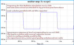
Here is what Multisim spice
thinks a 1 kHz squarewave would be like.
The load is using a capacitance across load
that probably would be close to a real life value
It is a very nice squarewave
without any disturbance like ringing or overshot
The upper rising, left, corner, which is slightly rounded
shows that -3dB is not at an extremely high value.
It is not the most fast amplifier, but on the other hand this fact makes it stable under many load conditions.
As I stated before, the -3dB frequency is limited to 30.000 Hertz
And this also contributes to good and low distortion figures.
lineup ... in his laboratory
hi
Here is what Multisim spice
thinks a 1 kHz squarewave would be like.
The load is using a capacitance across load
that probably would be close to a real life value
It is a very nice squarewave
without any disturbance like ringing or overshot
The upper rising, left, corner, which is slightly rounded
shows that -3dB is not at an extremely high value.
It is not the most fast amplifier, but on the other hand this fact makes it stable under many load conditions.
As I stated before, the -3dB frequency is limited to 30.000 Hertz
And this also contributes to good and low distortion figures.
lineup ... in his laboratory
Attachments
Microphone Amplifier 9 Volt Battery Discrete Regulator
I will see what I can do.
As you can see, the input BC550C is using like 566uA. (4.5-0.65V)/6k8
This means like 1-1.5 uA bias current. At the approximate gain of BC550C.
If using a simple resistor divider as input,
like in schematic R2-R6 47kohm-47kohm (giving like 23 kohm input impedance),
it may be difficult to get 1 Mohm input.
Making R2= 1M8 and R6= 2M2, wont work.
9 volt / (1.8M + 2.2M ) = 2.25uA ONLY!!!
and with 1.5uA into Q2 base, it would make a very big voltage drop
of the circuit operation voltage.
It would be far from 50% = 4.5V.
=====================================
But there are other ways to deal with this.
I have done a few new versions of this amp.
To avoid everything would be totally crazy
at only a few volts Drop from Battery,
this circuit has to be modified.
Two ways:
1. Use CCS, constant current sources, instead of emitter resistors.
This would also improve data quite a bit. Will be another amplifier, we could say.
I have built such a version.
2. Use my discrete 7.200 Volt low power consumption( 100uA ) discrete (3 transistors) REGULATOR
to provide constant operation voltage for this nice amp.
Actually this 7.200 Volt precision regulator
was developed for this very amplifer!
In the first place.
I have not published my regulator for 9 Volt batteries.
But I have mentioned it even so in this Davies visited Topic:
Discrete guitar preamp,
Post #4 ... by lineup
http://www.diyaudio.com/forums/showthread.php?postid=1073424#post1073424
--------------------------------------------------
This mic amplifier exists only as one great unique idea.
If I decide to go further, I would consider making 2 variants:
1. Like now, for normal audio 22 kohm input impedance.
Will suit most microphones, except for those really expensive professional ones.
But they wouldn't use my circuit, anyway.
2. One for 1 Mohm guitar input.
I would not have much troubles to do this.
There are 3-4 different ways to do it ... just counting those myself can think of!
--------------------------------------------------
As at least one person has shown interest in this unique amplifier.
( I have not seen this circuit idea before") )
)
So I may now have enough motivation to go on working with this one.
Currently I have 13-15 different amplifier projects & ideas going,
several of them with REALLY UNIQUE & IN MY OWN opinion good
audio circuits design elements and topology solutions.
Regards
lineup
Daveis said:Lineup,
And after the mic preamp is done can you change it to 1Megohm input impedance for guitar amp front-end use???
I will see what I can do.
As you can see, the input BC550C is using like 566uA. (4.5-0.65V)/6k8
This means like 1-1.5 uA bias current. At the approximate gain of BC550C.
If using a simple resistor divider as input,
like in schematic R2-R6 47kohm-47kohm (giving like 23 kohm input impedance),
it may be difficult to get 1 Mohm input.
Making R2= 1M8 and R6= 2M2, wont work.
9 volt / (1.8M + 2.2M ) = 2.25uA ONLY!!!
and with 1.5uA into Q2 base, it would make a very big voltage drop
of the circuit operation voltage.
It would be far from 50% = 4.5V.
=====================================
But there are other ways to deal with this.
I have done a few new versions of this amp.
To avoid everything would be totally crazy
at only a few volts Drop from Battery,
this circuit has to be modified.
Two ways:
1. Use CCS, constant current sources, instead of emitter resistors.
This would also improve data quite a bit. Will be another amplifier, we could say.
I have built such a version.
2. Use my discrete 7.200 Volt low power consumption( 100uA ) discrete (3 transistors) REGULATOR
to provide constant operation voltage for this nice amp.
Actually this 7.200 Volt precision regulator
was developed for this very amplifer!
In the first place.
I have not published my regulator for 9 Volt batteries.
But I have mentioned it even so in this Davies visited Topic:
Discrete guitar preamp,
Post #4 ... by lineup
http://www.diyaudio.com/forums/showthread.php?postid=1073424#post1073424
--------------------------------------------------
This mic amplifier exists only as one great unique idea.
If I decide to go further, I would consider making 2 variants:
1. Like now, for normal audio 22 kohm input impedance.
Will suit most microphones, except for those really expensive professional ones.
But they wouldn't use my circuit, anyway.
2. One for 1 Mohm guitar input.
I would not have much troubles to do this.
There are 3-4 different ways to do it ... just counting those myself can think of!
--------------------------------------------------
As at least one person has shown interest in this unique amplifier.
( I have not seen this circuit idea before
)So I may now have enough motivation to go on working with this one.
Currently I have 13-15 different amplifier projects & ideas going,
several of them with REALLY UNIQUE & IN MY OWN opinion good
audio circuits design elements and topology solutions.
Regards
lineup
Daveis
as I know you are not afraid some 2nd harmonic dist
but more concerned with low 3rd harmonic distortion
...
it might be interesting
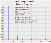
to see what fourier tells about this Lineup Audio Lab design
See attached Fourier Analys diagram.
Figures, at 0.5 mV input = 50 mV rms output
into 10 kohm load, with added 0.22nF capacitance in parallel.
-----------------------------------------------------------------------------
1 kiloHertz test signal
-------------------
1st: -000 dB
2nd: -077 dB
3rd: -111 dB
4th: -118 dB
5th: -119 dB
6th: -121 dB
7th: -124 dB
8th: -123 dB
9th: -122 dB
-----------------------------------------------------------------------------
Not bad! if I may say so,
for such a simple & good circuit, only 4T ... 4 ordinary low noise transistors
from
Lineup Audio Lab
as I know you are not afraid some 2nd harmonic dist
but more concerned with low 3rd harmonic distortion
...
it might be interesting
to see what fourier tells about this Lineup Audio Lab design
See attached Fourier Analys diagram.
Figures, at 0.5 mV input = 50 mV rms output
into 10 kohm load, with added 0.22nF capacitance in parallel.
-----------------------------------------------------------------------------
1 kiloHertz test signal
-------------------
1st: -000 dB
2nd: -077 dB
3rd: -111 dB
4th: -118 dB
5th: -119 dB
6th: -121 dB
7th: -124 dB
8th: -123 dB
9th: -122 dB
-----------------------------------------------------------------------------
Not bad! if I may say so,
for such a simple & good circuit, only 4T ... 4 ordinary low noise transistors
from
Lineup Audio Lab
Attachments
AudioAngel said:
- input impedance: switchable between 300, 600, 1200, and 2400 Ohms for optimal mic matching
What does the "optimal mic matching" term mean?
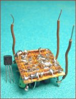
I"ve used this ballanced discreet design with good results in the Past ,It has very low Noise levels with low impedance mics which is most these days...
It can be easilly adapted for phantom power and if you need more Gain you can throw a dual opamp at the end.....
It uses up very little PCB space so you can put a Bunch in a small area and it uses very little Current so you can run a lot of Channels on a wimpy power supply.....
Cheers
It can be easilly adapted for phantom power and if you need more Gain you can throw a dual opamp at the end.....
It uses up very little PCB space so you can put a Bunch in a small area and it uses very little Current so you can run a lot of Channels on a wimpy power supply.....
Cheers
Attachments
Minion said:I"ve used this ballanced discreet design with good results in the Past ,It has very low Noise levels with low impedance mics which is most these days...
It can be easilly adapted for phantom power and if you need more Gain you can throw a dual opamp at the end.....
It uses up very little PCB space so you can put a Bunch in a small area and it uses very little Current so you can run a lot of Channels on a wimpy power supply.....
Cheers
Altec Lansing mic preamp?
Newbie questions
Hi guys,
This is my first post here, and I'm a beginner with anything other than tube amp builds. So I can solder, but I have no clue as to op-amps and FETS and such. I'd like to build a battery powered microphone pre-amp to boost the signal of a dynamic microphone, which will then run into one of the XLR inputs on a Zoom H4n. Because there will be a condenser mic into the other XLR, phantom power is going to be on.
The H4n will allow this, but I have to turn the gain way up and the preamp adds a lot of noise at that level to they dynamic mic. So I'd like to amplify the dynamic mic outside the recorder.
I can understand Minion's schematic, but have a couple of questions before I start on it.
1) Will running the output of that Pre-amp into an XLR with phantom power on cause any problems? If it will, I'll have to use an unbalanced input jack for my second channel.
2) Do I need to build a separate power supply to make a 9v battery give me 15V, or could I just use 2-9V batteries in series.
If building a 15v powersupply circuit is better, I'm game.
Thanks for taking the time to educate a beginner,
Todd
OK, I read more. Seems that I can just use one of these : LINEAR TECHNOLOGY|LTC1044CS8#PBF|DC/DC Charge Pump Converter IC | Newark.com
and a small cap and resistor to get 15V. But what about the issue of the phantom power on the H4n? Help please.
Todd
and a small cap and resistor to get 15V. But what about the issue of the phantom power on the H4n? Help please.
Todd
- Status
- This old topic is closed. If you want to reopen this topic, contact a moderator using the "Report Post" button.
- Home
- Amplifiers
- Solid State
- DIY Class-A mic-preamp