Hi,
it does not seem to matter whether a good circuit uses BJTs or lateral FETS or Vertical FETs in the output stage.
What seems to matter is how well the circuit is designed.
Similarly, good results can come from quasi complementary or fully complementary output devices.
Use a bad circuit and all of the above will sound bad.
Both vertical FETs and BJTs must have some form of thermal compensation to prevent the output stage going into thermal runaway if it deviates from normal running termperature.
Lateral FETs seem to survive without thermal compensation and this must be due to the negative temperature coefficient that is inherent in their manufacture. Look at the way Vbe of BJTs and Vds of Vert Fets varies with junction temperature and compare these to the Vds vs Tj of a lateral FET to see the difference as it heats up.
Do not substitute vertical FETs into a circuit designed for lateral FETs without thoroughly checking the design and altering/adding, where necessary, any components to ensure the thermal stability of the modified circuit.
You have been warned by many others, hopefully you can now go a look for the data and see for yourself.
ilizm
So can you post some irfp mosfet amplifier link around +/- 70 that YOU CAN TRUST :
there are lots of schematics here and I donk know what to choose: I am new to this forum and I should search an red it thoroughly
so
velikigrizli@gmail.com
try posting something here or give some link of not too much trouble
Yes I considered this amplifier you mentioned before from Quasi:
If you wold have to buld or wolud need aplifier what wold you choose mosfet or bipolar ?
I dont know why he http://users.swing.be/edwinpaij/ampli_mosfet_360_w.htm
refuses using temperature tontrol transisotr for bias that is mounted near optput mosfets :
Every bipolar and mosfet amplifier HAVE THIS BIAS TEMPERATURE ontrol transistor !!
So mosfet have "mekshi zvuk" not so "sharp"
?
So can you post some irfp mosfet amplifier link around +/- 70 that YOU CAN TRUST :
there are lots of schematics here and I donk know what to choose: I am new to this forum and I should search an red it thoroughly
so
velikigrizli@gmail.com
try posting something here or give some link of not too much trouble
Yes I considered this amplifier you mentioned before from Quasi:
If you wold have to buld or wolud need aplifier what wold you choose mosfet or bipolar ?
I dont know why he http://users.swing.be/edwinpaij/ampli_mosfet_360_w.htm
refuses using temperature tontrol transisotr for bias that is mounted near optput mosfets :
Every bipolar and mosfet amplifier HAVE THIS BIAS TEMPERATURE ontrol transistor !!
I could say that most of the MOSFET amps I have heared that I would say were 'good' tended to sound slightly more 'withdrawn', or, perhaps, better said, less forward in the midrange than bipolar transistor amps - but I can't say that either way is better.
So mosfet have "mekshi zvuk" not so "sharp"
?
Hi Med,
that circuit you linked to does not show any component values or component types.
He wants to sell you the information to allow you to copy his design.
I can tell from looking at the schematic that it should be using Lateral FETs and he is telling lies by saying it will be cheap to copy.
that circuit you linked to does not show any component values or component types.
He wants to sell you the information to allow you to copy his design.
I can tell from looking at the schematic that it should be using Lateral FETs and he is telling lies by saying it will be cheap to copy.
Look at this thread: http://www.diyaudio.com/forums/showthread.php?s=&threadid=86370
I built amp very similar to yours with IRFP240 and it works quite good.
I built amp very similar to yours with IRFP240 and it works quite good.
kubeek said:Look at this thread: http://www.diyaudio.com/forums/showthread.php?s=&threadid=86370
I built amp very similar to yours with IRFP240 and it works quite good.
using vertical only with resistor bias current seting without termal runaway protection?
hmm ok ill look at the thread and see
kubeek said:No, with thermal compensation. Only the basic symmetrical design with double LTP and the VAS are the same.
I can send you the original scan of the magazine, altered Eagle schematic and circuit board.
velikigrizli@gmail.com
thanks
So it has thermal protection bipolar for setting bias current?
So how it sounds ?

Sounds good
I use it as a bass amp, driving only one 15" speaker in closed box (in the size of washing machine) so without a horn I can´t really tell how exactly it sounds...
For thermal compensation it uses another mosfet, buz11 I guess.
I will send you the .pdf and the other things.
I use it as a bass amp, driving only one 15" speaker in closed box (in the size of washing machine) so without a horn I can´t really tell how exactly it sounds...
For thermal compensation it uses another mosfet, buz11 I guess.
I will send you the .pdf and the other things.
kubeek said:Sounds good
I use it as a bass amp, driving only one 15" speaker in closed box (in the size of washing machine) so without a horn I can´t really tell how exactly it sounds...
For thermal compensation it uses another mosfet, buz11 I guess.
I will send you the .pdf and the other things.
What about for general listening not only bass : bass can use high distorsion ampliifier D class without differences in sound qualitiy
o you maybe have less power version +/- 70V
http://users.swing.be/edwinpaij/ampli_mosfet.htm
kubeek said:You have it on email.
I have it only in practice room, with no real-word speaker at hand.
I really don´t know, but it shouldn´t be bad, as this style of amp seems to appear all the time without any negative comments (except the thermal compensation).
and too low current for output stages because of high capacitience of irfp-s
It didnt come yet GMAIL do not ALLOW compress files: send it here
velikigrizli@unlimitedmail.org
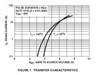
This graph (taken from IRFP240 datasheet) seems to show the behaviour you describe only at very high currents.
In a real application you aren't going to use 10A bias per fet...thus the tempco is positive for the operating conditions and it turns negative once your fet is already cooked.
Cheers
Andrea
In a real application you aren't going to use 10A bias per fet...thus the tempco is positive for the operating conditions and it turns negative once your fet is already cooked.
Cheers
Andrea
Attachments
medogrizli said:WHY everybody claim that VMOS: vertical mosfet has TERMAL RUNAWAY problems :
VMOS has NEGATIVE temperature characteristic more heat less current !!!
Everyone claims it becaue for the range of currents in question it's true. You need to work on understanding datasheets.
ilimzn said:
Everyone claims it becaue for the range of currents in question it's true. You need to work on understanding datasheets.
Thats from Biljanovic book
ok you are right I have to check the datasheets thoroughly
But if the current exceeds 10A the current will stop inceasing : shall the mosfets burn?
10A*70V 700W / 4 mosfets = 175 W maximum per mosfet : if the fuse is 5-6A fuse will burn first before mosfets heat up
For example irfp can dissiapte around 200W if good coller
hmm
but if we use bias current setting transistor there is no need to concern
richie00boy said:Er no, 10A per MOSFET so that's 700W it tries to pass before the inbuilt burn resistance works...
no 10A per ALL mosfets
- Status
- This old topic is closed. If you want to reopen this topic, contact a moderator using the "Report Post" button.
- Home
- Amplifiers
- Solid State
- 2SK/irfp lateral vertical mosfet amplifier HELP ??