looks like it can work
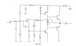
it is a basic concept for simple power amplifier
that has been used a very long time in many designs
See for example Elliott Sound Products
project 36
the wellknown DoZ simple amplifier
http://sound.westhost.com/projects-1.htm
Now,
you are far from a good amplifier just by a basic topology
- components has to chosen, like a Lateral MOSFET complementary pair
- components values has to be set in a good way
- finally, the practical circuit has to be built
- together with a power supply, that is suitable for this circuit
But a good start
and
when you have not made up your mind for any details
then not many details can be questioned
and not much to add a comment about
")
Regards
lineup
it is a basic concept for simple power amplifier
that has been used a very long time in many designs
See for example Elliott Sound Products
project 36
the wellknown DoZ simple amplifier
http://sound.westhost.com/projects-1.htm
Now,
you are far from a good amplifier just by a basic topology
- components has to chosen, like a Lateral MOSFET complementary pair
- components values has to be set in a good way
- finally, the practical circuit has to be built
- together with a power supply, that is suitable for this circuit
But a good start
and
when you have not made up your mind for any details
then not many details can be questioned
and not much to add a comment about
Regards
lineup
I did something like this about 20 years ago and was not impressed (Hitachie mosfets) . To me a waste of good devices !
This circuit or a very near design is also featured in a B,banie publication "see the maplin cat "To me the worry is that of driving the output devices capacitances with this driver stage config
Regards Trevor
This circuit or a very near design is also featured in a B,banie publication "see the maplin cat "To me the worry is that of driving the output devices capacitances with this driver stage config
Regards Trevor
You need to have a larger than normal driver stage current in order to drive the out put devices your drawing is only that some values would assist greatly in aiding .
Going back to the driver stage I think you need about 25 mA in order to look after the gate capacitance
also I have not noted any gate protection for the output devices
this could be most imprtant
You will also require some gate stopper resistors on the output devices approx 220 ohm or your amplifier could oscillate and self destruct !!!
regards Trev

BTW you mention the inclusion of R1 as in your schematic above as a form of current dumping. While it is indeed that, it is by no means comparable to what was used in the Quad 405 and other amps - there it is a bridge arrangement which effectively nulls out the 'class C' output stage, and is a form of error feedforward.
BTW
Current dumping I don,t think so! There is no feed back bridge network to change the Gm of the driver stage output stage interface during handover to the boosters
I have seen similar schemes as this and though they work in a fashion it will never measure well!
Keep the capacitor coupling as it helps to protect your spk,s
I have yet to see a pair of DC coupled ears
Regards Trev
ilimzn said:BTW you mention the inclusion of R1 as in your schematic above as a form of current dumping.
I see nowhere R1 mentioned in this thread.
For clarity and give us other opportunity to know what is talked about here
a link to other topic where R1 error correction is mentioned
may be good information.
Even if this is not on the topic of johndiy.
Not yet anyway.
Regards
lineup
Lineup Class B Audio Designs & Error Corrections Ltd
London West End

latala said:BTW Current dumping I don't think so!
It is definitely 'current dumping' - the output stage dumps current whenever the drop over R1 is sufficiently hight to bias it into base current.
But, you are right, it's not the same as Quad current dumping - which is, in fact, a very ill-chosen name, as the intention of the inventor was a form of error feedforward - the current dumping part only refers to the class C output stage, while the real clever bit is in the bridge network you mention below:
There is no feed back bridge network to change the Gm of the driver stage output stage interface during handover to the boosters
Also, I agree with the following:
I have seen similar schemes as this and though they work in a fashion it will never measure well!
This is because the original invention applied in the Quad 405 practically eliminates the output stage as a contributor to the total transfer function. This has other interesting repercussions, most notably to amplifier stability - a 3-stage amp with such an output stage behaves as a 2-stage amp. The down side is the bridge parts figure in the character of the output impedance of the amp, which begets an inductive component, and interracts (not always positively!) with the load.
What Wavebourn has shown does no such thing. It attempts to linearize the transfer characteristic of the class C output stage by providing a default resistive path from the high biassed or class A driver stage. This actually softens the knee in the transfer characteristic of the output stage some, effectively enlarging the size of the crossover area. In theory, it alowes a much lower bias current for the output stage - the lower, the smaller R1, but it also redistributes the work that the driver has to do ves the output stage. There is also a nested amplifier with it's own feedback loop which serves to reduce the resultant distortion, the rest to be handled by the GNFB. Unfortunately, the practical side is not as well concieved, including a single diode to provide at least some bias to the bases of the transistors, in the manner shown, makes the crossover region highly asymetrical. The fix is quite trivial and involves the addition of one more resistor, this makes the crossover region much more symetrical. I experimented with this sort of topology about 20 years ago, in a number of simple amps aimed at PA applications, where absence of any trimming components was a plus, and the high(er) distortion was not an issue.
lineup said:I see nowhere R1 mentioned in this thread.
For clarity and give us other opportunity to know what is talked about here
My bad, Lineup - in t he edit I lost 'in another thread'. Here is the thread:
http://www.diyaudio.com/forums/showthread.php?s=&threadid=87718&perpage=10&pagenumber=6
see speciffically the penultimate post in the thread, also in a previous post by Wavebourn in the same thread, a mention of how Quad's CD scheme was an attempt to patent something simple that Wavebourn has supposedly done, that being the inclusion of R1 as in the above schematic.
latala said:BTW
Current dumping I don,t think so!
No Trev, it is not a current dumping. Nothing dumps a dirty current, just an approximation of linear transfer function using couple of semi-linear parts, with variable feedback. Anyway, in any amp feedback is variable because distortions mean a variable gain, but in this particular case it is built with nonlinearities in mind, so they are known and controlled.
Now leave only one pair of output emitter followers, increase emitter resistors, and add in parallel complememntary pair of strong IR HEXFETs to get a 3-step approximation.
That amplifier in 1977 worked well. I believed then in grown up engineers, I thought they don't do such approximation because it is a cheating to get satisfactory results by cheap methods. It was made for bass guitar, so I did not care of slightly bigger distortions, but it performed surprisingly well for HiFi.
If to use modern components, high Ft and HFE transistors with no loss of HFe in the working current range, and faster OpAmp, results are much better. Actually, what is needed from them, it is the speed of gain changing to compensate distortions.
...Now let's return back to the 1'st posting. If transistors are fast and have high HFE, they will easilly switch gain so crossover distortions in under-biased FETs will not be heard. Anyway, we every day hear such fast switchings made in purpose, when use CD players and other electronics that uses DACs.
jacco vermeulen said:Wavebourn,
Skazátv zdrávstvuyte do Veronika
Very nice
Dzenkuje jacco vermeulen!
In current projects I use 3-step approximation, with additional powerful FETs and a servo OpAmp on infrasounds only. Instead of OpAmp input I use couple of vacuum tubes. I do not run for symmetrical distortions, I don't understand why somebody may prefer them. If level of distortions is very low it does not matter, symmetrical are they, or not. If it is higher, symmetrical distortions sound less natural.
Wavebourn said:Dzenkuje
You're welcome, nice to see a sense of humor.
The SE chassis made by Fox on your forum is very impressive.
(that Maria Gorin in Moscow is cute, i should get back into Tai Chi, Chi Kung and NLP stuff)
Wavebourn said:...If transistors are fast and have high HFE, they will easilly switch gain so crossover distortions in under-biased FETs will not be heard. Anyway, we every day hear such fast switchings made in purpose, when use CD players and other electronics that uses DACs.
I'm sorry but this is not true. DACs are not inside a feedback loop, neither can you hang an anti-alias or reconstruction filter at the output of your amp. Also you can't really say that a DAC transfer function changes with amplitude, or that it changes gain. I really don't see how you can compare the two.
- Status
- This old topic is closed. If you want to reopen this topic, contact a moderator using the "Report Post" button.
- Home
- Amplifiers
- Solid State
- bobby the 60w mosfet