Dear all,
Over the last few months I've built several prototypes of power amplifers. I started with OpAmp driven circuits (which sounded OK), but decided to try a SS design as well, just to be 'sure'. The first (working ) protoype sounded so much better I decided to stick with that (this is personal preference of course, besides I can only compare it to an 8 yr old Phony(TM) audio set).
From various sources combined (mostly Elektor) I ended up with this design for a symmetric (class AB) power amplifier.
The only difference between this one and my last working prototype is the Vbe multiplier (prototype has trim-pot between C and E) and the end transistors (BD911/912 instead of Sanken types since BD91x is somewhat cheaper to experiment with, although I did use the Sankens in a version without the cascodes in the LTPs successfully).
I would welcome any thoughts or comments you might have on this design.
Thanks!
Remco
P.S. One thought already: R2 & R102 are probably superfluous, the reason I kept them in was because I like to stick as much maybe's in a PCB design as possible, it's always easier to leave components out and bridge them than to insert new components in an exisiting PCB")
Over the last few months I've built several prototypes of power amplifers. I started with OpAmp driven circuits (which sounded OK), but decided to try a SS design as well, just to be 'sure'. The first (working
) protoype sounded so much better I decided to stick with that (this is personal preference of course, besides I can only compare it to an 8 yr old Phony(TM) audio set).From various sources combined (mostly Elektor) I ended up with this design for a symmetric (class AB) power amplifier.
The only difference between this one and my last working prototype is the Vbe multiplier (prototype has trim-pot between C and E) and the end transistors (BD911/912 instead of Sanken types since BD91x is somewhat cheaper to experiment with, although I did use the Sankens in a version without the cascodes in the LTPs successfully).
I would welcome any thoughts
or comments you might have on this design.Thanks!
Remco
P.S. One thought already: R2 & R102 are probably superfluous, the reason I kept them in was because I like to stick as much maybe's in a PCB design as possible, it's always easier to leave components out and bridge them than to insert new components in an exisiting PCB
Attachments

It is bad idea to shunt Zener (LED) by a capacitor. The capacitor will not filter unwanted noise because of the low dynamic impedance of the Zener (LED). For reducing hum you can split R7(R107) as 5.1k + 5.1k, and connect C4 (C104) (better 100u) between supply rail and the common point of 5.1k resistors. If you aware about hf LED noise, you can use R-C filter, i.e. put an extra resistor between D1 and base of Q5 and reconnect C3 between supply rail and base of Q5.
The voltage swing on the Q8(Q108) base will be limited by (30-UD2-0.7)=25V. The excess voltage drop on the output device will be 10V at maximum current, would you like to warm up your room? Your 30V supply should be 40V.
Why do you use emitter bypassing in Q6(Q106)?
The voltage swing on the Q8(Q108) base will be limited by (30-UD2-0.7)=25V. The excess voltage drop on the output device will be 10V at maximum current, would you like to warm up your room? Your 30V supply should be 40V.
Why do you use emitter bypassing in Q6(Q106)?
Rambi said:Dear all,
Over the last few months I've built several prototypes of power amplifers. I started with OpAmp driven circuits (which sounded OK), but decided to try a SS design as well, just to be 'sure'. The first (working
From various sources combined (mostly Elektor) I ended up with this design for a symmetric (class AB) power amplifier.
The only difference between this one and my last working prototype is the Vbe multiplier (prototype has trim-pot between C and E) and the end transistors (BD911/912 instead of Sanken types since BD91x is somewhat cheaper to experiment with, although I did use the Sankens in a version without the cascodes in the LTPs successfully).
I would welcome any thoughts
Thanks!
Remco
P.S. One thought already: R2 & R102 are probably superfluous, the reason I kept them in was because I like to stick as much maybe's in a PCB design as possible, it's always easier to leave components out and bridge them than to insert new components in an exisiting PCB
I had a look at your amp.
I like it.
BD911 are good working horse devices.
Can take a lot of heat for being TO220
A choice I also like.
Regarding the details you will get more opinions
by others.
Enjoy your project.
It is yours!
You have done your homework!
My only suggestion for now is that you try this and see what it sounds like: Remove R56 and C51. Add 100 ohm resitors between Q9 base and emitter and Q109 base and emitter.
I believe you should have decoupling across your CCS LEDs - it's nothing to do with LED noise as you probably already know.
BAM
dimitri said:It is bad idea to shunt Zener (LED) by a capacitor. The capacitor will not filter unwanted noise because of the low dynamic impedance of the Zener (LED). For reducing hum you can split R7(R107) as 5.1k + 5.1k, and connect C4 (C104) (better 100u) between supply rail and the common point of 5.1k resistors. If you aware about hf LED noise, you can use R-C filter, i.e. put an extra resistor between D1 and base of Q5 and reconnect C3 between supply rail and base of Q5.
The voltage swing on the Q8(Q108) base will be limited by (30-UD2-0.7)=25V. The excess voltage drop on the output device will be 10V at maximum current, would you like to warm up your room? Your 30V supply should be 40V.
Why do you use emitter bypassing in Q6(Q106)?
C6/C106 bypasses R8/R108 for audio (but not for DC), seems to give it more 'oomph'. Since my latest PCB has Q7/Q107 mounted directly to the heatsink I could probably just as well lower R8/108 and ditch the capacitors.
Using a cascode will not change the voltage drop over, or power disipation by, the output devices, that's determined by supply and output voltage (and of course the kind of load). It does limit the maximum output swing by a few volt, but I figured that disadvantage was compensated because it allows me to use BC5x devices in the VAS.
As for the supply: I use a 2*30V toroid, after rectifying etc the output voltage is more like 40V (slightly higher even).
R56 can be a factor 10 lower, I'll try it and see (hear) what it does to the sound.
Thanks for your comments!
Remco
traderbam said:You have done your homework!
My only suggestion for now is that you try this and see what it sounds like: Remove R56 and C51. Add 100 ohm resitors between Q9 base and emitter and Q109 base and emitter.
I believe you should have decoupling across your CCS LEDs - it's nothing to do with LED noise as you probably already know.
BAM
I'll try a lower value for R56 (appr. 100 Ohm instead of 1200) first, since that's easier to do. Using two resistors and connecting the 'middle' to the output (like you describe) is one of the 'options' I did not include in the PCB design (but should have...). Anyone out there ever tried and compared these two variations? (fig.13 A and B from http://www.dself.demon.co.uk/dipa.htm#5 )
Thanks!
Remco
Anyone out there ever tried and compared these two variations?
-----------------------
Yes, I’d tried and compared these configurations many many years ago… I can address you to my article "Building Better Buffers," Electronics World + Wireless World, 1992, Nov., pp.931-934.
Yes, Mr.Self is right, that his Fig.13(b) gives much better turn-off, but another drawback of Fig.13(a) is that the driver transistors will also switch off, after the output ones, one more singularity! In Fig.13(b) the driver transistors will work with nearly constant collector current (class A) during the whole cycle.
dimitri said:It is bad idea to shunt Zener (LED) by a capacitor. The capacitor will not filter unwanted noise because of the low dynamic impedance of the Zener (LED). For reducing hum you can split R7(R107) as 5.1k + 5.1k, and connect C4 (C104) (better 100u) between supply rail and the common point of 5.1k resistors. If you aware about hf LED noise, you can use R-C filter, i.e. put an extra resistor between D1 and base of Q5 and reconnect C3 between supply rail and base of Q5.
I do not agree totally. Its okay to remove C2 and C102 but keep C3 and C103.
Why?
To bypass the LED's at high frequency so you not only have a low impedance at LF but also at HF.
Then again split the circuit as Dimitri says but reduce the R in the RC filter to 10 - 20 ohm to prevent making a resonance circuit with C3 and the LED.
-------
Be carefull with large size film caps like C51. Larger values more series induction.
-------
Add a small base resistor (1 - 10Ohm) on Q9 and Q109 to prevent oscillation in the output devices.
The i can only say.... Nice circuit!... go build it.
Sonny
Rambi said:
Over the last few months I've built several prototypes of power amplifers. I started with OpAmp driven circuits
Hi,
I'm currently in the process of building a similar amplifier. Just curious, do you have any gain/phase plots or scope pictures of sine/triangle/square waveforms at test frequencies? Say 1K,10K,20K, 50K, and 100K @8Ohms load or so. Also have you tested stability with any comples loads?
I'd be really curious to see how your amp responds.
Also, Am I mistaken, or is the LF411 an integrator to compensate for the DC-Bias? I'd never seen that done, but I've been thinking about trying it (Soon).
-Dan
Re: Re: symmetric amplifier
Umm, no sorry. I do have a scope, but no digital camera.
(And at the moment the design is still changing rapidly enough not to use an ordinary camera, certainly with the excellent feedback and fresh ideas from this forum, thanks all!)
Good idea though, I'll see if I can beg, steal, or borrow a digital camera for the final design (which should be around the time pigs fly, there's always another tweak to test...)
The only complex loads it has seen are various el-cheapo loudspeakers each with variyng qualities of cables (don't have a power resistor).
Out of curiosity: is your amplifier project already in a stage where you have any schematics (that you'd like to share)?
Yep, it is. One of the earlier design I tried to build was the Elektor HexFet power amp, which doesn't use such a DC compensation circuit. It did work, but the DC offset was too unstable to my liking (nice to see the effect of breathing on the LTPs though).
This circuit seems to do the job quite nicely and as a bonus it eliminates an electrolytic in the feedback path. Downside is that it needs a capacitor at the input, but that doesn't have to be as big (or an electrolytic). Come to think of it: It should be possible to connect it to the other side of the LTPs with some tweaking.
It does need a few seconds to stabilize at startup (depending on component values & matching, latest one starts from appr. -1 V and needs a few seconds to get close to zero).
Remco
dkemppai said:
Hi,
I'm currently in the process of building a similar amplifier. Just curious, do you have any gain/phase plots or scope pictures of sine/triangle/square waveforms at test frequencies? Say 1K,10K,20K, 50K, and 100K @8Ohms load or so. Also have you tested stability with any comples loads?
I'd be really curious to see how your amp responds.
Umm, no sorry. I do have a scope, but no digital camera.
(And at the moment the design is still changing rapidly enough not to use an ordinary camera, certainly with the excellent feedback and fresh ideas from this forum, thanks all!
)Good idea though, I'll see if I can beg, steal, or borrow a digital camera for the final design (which should be around the time pigs fly, there's always another tweak to test...)
The only complex loads it has seen are various el-cheapo loudspeakers each with variyng qualities of cables (don't have a power resistor).
Out of curiosity: is your amplifier project already in a stage where you have any schematics (that you'd like to share)?
Also, Am I mistaken, or is the LF411 an integrator to compensate for the DC-Bias? I'd never seen that done, but I've been thinking about trying it (Soon).
-Dan
Yep, it is. One of the earlier design I tried to build was the Elektor HexFet power amp, which doesn't use such a DC compensation circuit. It did work, but the DC offset was too unstable to my liking (nice to see the effect of breathing on the LTPs though
).This circuit seems to do the job quite nicely and as a bonus it eliminates an electrolytic in the feedback path. Downside is that it needs a capacitor at the input, but that doesn't have to be as big (or an electrolytic). Come to think of it: It should be possible to connect it to the other side of the LTPs with some tweaking.
It does need a few seconds to stabilize at startup (depending on component values & matching, latest one starts from appr. -1 V and needs a few seconds to get close to zero).
Remco
Re: Re: Re: symmetric amplifier
b]Good idea though, I'll see if I can beg, steal, or borrow a digital camera for the final design (which should be around the time pigs fly, there's always another tweak to test...)
The only complex loads it has seen are various el-cheapo loudspeakers each with variyng qualities of cables (don't have a power resistor).[/b]
Tell me about the tweaks... ...I've got an amp that's almost done, 6 years it's bee almost done! I can get some images from my scope... ...if interested let me know.
My new design is mid stream, so no schematics yet. (Soon, I hope). Right not I'm focusing on phase and linearity while trying to keep the thing stable. Phase shift is around -3.5 degrees at 20Khz. (-15 deg at 100Khz) I was shooting for less than 1 degree at 20k, but that's getting difficult. Even now it's just slightly under damped.
Response at small signals is from DC to around 300Khz, dropping to 100Khz at 40W (RMS) output. 70W at 50Khz, and so on. (I consider the limit of maximum power at the point where I can start to see distortion on the scope) It'll push a few hundred watts at 20Khz, but only for short bursts (small load/heatsinks)
I really need a %THD meter, and way to measure noise levels! (Any good recomendations?)
As for the Integrator, been tossing the idea around. Just trying to think of a few places to integrate it into circuit, where it'll be unobtrusive. I may 'borrow' some of your circuit for that.
-Dan
Tribute to TRADERBAM - traderbam is one of our members
traderbam - dear friend
I like you more than most of these "yes-sayers"
you make me think
you keep me alert
traderbam
In other words
I like you very much
So much that one day I might build me a traderbam amplifier
remember?
I do
halojoy
of sweden and jesus
---------------------------------------------------------
*this is a transcription of a post of mine
in thread "greening a classic"
where traderbam has made a lot of nice thinking
Re: Re: Re: Re: symmetric amplifier
I'm always interested!
I only have simulations for phase shift etc. With component values as shown it's about 10 degrees at 20kHz.
(IIRC that is. I'm in the middle of installing my new computer. Once I have everything back on-line I'll see if I can post an updated schematic with some of the suggestions integrated).
Remco
dkemppai said:Tell me about the tweaks... ...I've got an amp that's almost done, 6 years it's bee almost done! I can get some images from my scope... ...if interested let me know.
I'm always interested!
My new design is mid stream, so no schematics yet. (Soon, I hope). Right not I'm focusing on phase and linearity while trying to keep the thing stable. Phase shift is around -3.5 degrees at 20Khz. (-15 deg at 100Khz) I was shooting for less than 1 degree at 20k, but that's getting difficult. Even now it's just slightly under damped.
I only have simulations for phase shift etc. With component values as shown it's about 10 degrees at 20kHz.
(IIRC that is. I'm in the middle of installing my new computer. Once I have everything back on-line I'll see if I can post an updated schematic with some of the suggestions integrated).
It's not mine; as I said in my first post most of it is bits and pieces from various designs (mostly Elektor stuff). The Crescendo Millenium Edition uses an integrator like this. After some searching I found that the 'Power Amp' (also Elektor) uses a variation with an integrator connected to the 'other' sides of the LTPs.
As for the Integrator, been tossing the idea around. Just trying to think of a few places to integrate it into circuit, where it'll be unobtrusive. I may 'borrow' some of your circuit for that.
Remco
Nice work of Yours!
It is yours.
We all have learnt from other & eachother.
That's human culture.
It's not mine; as I said in my first post most of it is bits and pieces from various designs (mostly Elektor stuff). The Crescendo Millenium Edition uses an integrator like this. After some searching I found that the 'Power Amp' (also Elektor) uses a variation with an integrator connected to the 'other' sides of the LTPs.
I have studied every single Elektor amplifier in its details.
I have almost complete collection from 1985 of Swedish elektor.
A good way of learning Electronics - not only for Audio.
halojoy, traderbam, Nelson Pass, peranders or AKSA
we all use what was brought to us by culture.
But then we add a touch of ourselves.
Our own contribution to the sum of human culture.
And so do you, my friend Rambi
Enjoy yourself - You are great!
/halojoy the great
Images... ...1 of 2
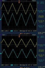
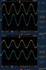
Cool, here are a few images. (I hope you can find that camera to snap a few to post also )
The measurements are pretty self explanatory, as to frequency, phase, and gain (can be calculated from peak to peak) Blue trace is output signal into 8 ohm 100W non inductive resistor. Yellow trace is input into amplifier.
I was going to grab a few more, but I left it run at high power a little too long... ...POP! SNAP! followed by orange flame from the fets, and lots of magic smoke. So, until I rebuild (In about an hour) you'll have to settle for the 100Khz and single 10Khz traces...
Also, the amp was running at +- 50 Volt rails, +- 70 volts seems to improve linearity at high frequencies.
-Dan
(EDIT Typos!)
Rambi said:I'm always interested!
Cool, here are a few images. (I hope you can find that camera to snap a few to post also )
The measurements are pretty self explanatory, as to frequency, phase, and gain (can be calculated from peak to peak) Blue trace is output signal into 8 ohm 100W non inductive resistor. Yellow trace is input into amplifier.
I was going to grab a few more, but I left it run at high power a little too long... ...POP! SNAP! followed by orange flame from the fets, and lots of magic smoke. So, until I rebuild (In about an hour) you'll have to settle for the 100Khz and single 10Khz traces...
Also, the amp was running at +- 50 Volt rails, +- 70 volts seems to improve linearity at high frequencies.
-Dan
(EDIT Typos!)
Attachments
- Status
- This old topic is closed. If you want to reopen this topic, contact a moderator using the "Report Post" button.
- Home
- Amplifiers
- Solid State
- symmetric amplifier