Hi Chris,
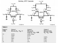
Did you compare your diff input Zener biased JFET cascode circuit with a Vt self biased cascode similar to what Mr. Borbley often uses? The 2SK246 JFET in the attached circuit has a larger Vt than a 2SK170(2SK389), and this Vt difference establishes the cascode bias. I've gotten good results with the Borbley circuit, but the design requires careful JFET testing and matching.
The literature data shows the lowest distortion with a bipolar diff input and bipolar cascode, and next lowest with a JFET diff input and biased bipolar cascode. Borbley suggests that the JFET-JFET cascode has reduced 3rd harmonic distortion, reduced low signal noise with a high input impedance(over 50 ohms), and favorable thermal tracking, which makes it the best audio topology.
Attachments
LineSource said:Borbley suggests that the JFET-JFET cascode has reduced 3rd harmonic distortion, reduced low signal noise with a high input impedance(over 50 ohms), and favorable thermal tracking, which makes it the best audio topology.
LineSource,
good point,
very good point!
")
LineSource said:Hi Chris,
Did you compare your diff input Zener biased JFET cascode circuit with a Vt self biased cascode similar to what Mr. Borbley often uses? The 2SK246 JFET in the attached circuit has a larger Vt than a 2SK170(2SK389)
2sk246 (not to easy to get those FETs today) self biased offer only 2-2.5V for cascoded device. It is very hard to good match all four devices.
Zenner biased JFET do the same thing much easier
Hi Mihai,
Firstly, I want to run my FETs with a higher, no fuss Vds (hand selecting fets is an incredible pain). Ib is not really an issue here either as it is equal on both sides and a non issue as far as I know. I could be wrong, but someone would have to explain it to me.
Secondly, I never use current diodes. Rather imperfect devices, a simple LED-BJT setup works better.
-Chris
I did read it. I read it again and thought about it. Doesn't wash from what I know.Please read carfully all the reasons i had in using JFETs as cascode device.
Firstly, I want to run my FETs with a higher, no fuss Vds (hand selecting fets is an incredible pain). Ib is not really an issue here either as it is equal on both sides and a non issue as far as I know. I could be wrong, but someone would have to explain it to me.
Secondly, I never use current diodes. Rather imperfect devices, a simple LED-BJT setup works better.
I'd have to see it to accept it, it's possible. Thermal tracking? Now I'm truly lost! I can see why this might be a problem with J-fets, but BJT's? Your D-S voltage would be set by the voltage on the bases (give or take a few mV).Borbley suggests that the JFET-JFET cascode has reduced 3rd harmonic distortion, reduced low signal noise with a high input impedance(over 50 ohms), and favorable thermal tracking, which makes it the best audio topology.
-Chris
anatech said:Hi Mihai,
... I never use current diodes. Rather imperfect devices, a simple LED-BJT setup works better.
I'd have to see it to accept it, it's possible. Thermal tracking? Now I'm truly lost! I can see why this might be a problem with J-fets, but BJT's? Your D-S voltage would be set by the voltage on the bases (give or take a few mV).
-Chris
Hi Chris,
Where did you see diode used as a CCS Vref component? D2 is used as Vref for cascode device Q11.
I dont see your point regading thermaltrak (NJL's) devices

anatech said:Hi Mihai,
You were referring to Borbley's work, were you not?
-Chris
Sorry, my mistake, thermal traking is not the same with TermalTrack(TM)
In my schematic, Vds for active JFET is 12V not 2.5V as per Borbely's topology with 2sk389/2sk246
Have a nice night,
Mihai
pinkmouse said:Had a boring afternoon as my ISP was down.
Your ISP should crash more often. Looks promising.
I really want to hear this amplifier. So many good words of Symasym.Shawn.
pinkmouse said:Had a boring afternoon as my ISP was down.
Hi Al,
Nice work, go on and finish it !
May I sugest to replace R35 with a 500ohm trimpot for proper bias adjusting.
Mihai
Hi pinkmouse,
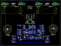
Never underestimate the power of strategically placed jumpers. Running your B+ and B- through heavy jumpers may have a positive side effect. Your sensing diode connections could be run through ribbon wire back to the bias circuit, thinking 20 GA wire here.
-Chris
Never underestimate the power of strategically placed jumpers.
Running your B+ and B- through heavy jumpers may have a positive side effect. Your sensing diode connections could be run through ribbon wire back to the bias circuit, thinking 20 GA wire here.-Chris
Hi Al,
You could use coloured wire.
-Chris
Edit: twist some Cat-5 wires together, it will sound amazing!
I hear you. Consider the trace or a jumper a component. You can put way more copper in a jumper than is easily done with a trace.Yeah, true enough, it just offends my aesthetic sensibilities.
You could use coloured wire.
-Chris
Edit: twist some Cat-5 wires together, it will sound amazing!
anatech said:You could use coloured wire.
Mmmm, pink...
Hello !!
I'm finally building my Symasym !
It was laying on the shelf a long time !
But building, I noticed that the Symasym of the picture is using a wire instead R16/19 (22Ohms), and have sc5200/sa1943 output.
Using with the stock 3281 / 1302 I must use 22R to R16/19 right ?
Thanks !!!!
I'm finally building my Symasym !
It was laying on the shelf a long time !
But building, I noticed that the Symasym of the picture is using a wire instead R16/19 (22Ohms), and have sc5200/sa1943 output.
Using with the stock 3281 / 1302 I must use 22R to R16/19 right ?
Thanks !!!!
- Status
- This old topic is closed. If you want to reopen this topic, contact a moderator using the "Report Post" button.
- Home
- Amplifiers
- Solid State
- Symasym - the sequel