

anatech,
Since you're a mod, please delete this post if you think that it is in the wrong thread or if there is a better thread for it. I didn't want to disturb the original thread, they seem to be on to something and I didn't want to disrupt their progress.
I have been messing around with symasym5.3, just testing stuff, and I found that the bias on Q13 and Q14 wasn't balanced and wondered that if I messed with the resistor values that the distortion might decrease slightly. I know that I'm not qualified to mess with this stuff but I wondered if anyone really bothers with the small stuff like that.
I have my schem in the attachment.
I increased R17 (in my schem) to decrease the bias voltage on Q14 to better match it with Q13 which made the biases around 710mV.
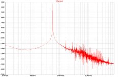
This is the FFT before the optimization:
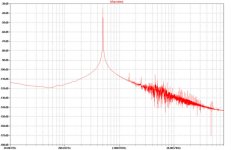
This is it after the optimization:
NOTE: My site manager delays the time it takes for things to actually show up on the website, so if you don't see pictures, come back later
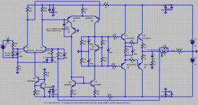
Here is my schem:
Since you're a mod, please delete this post if you think that it is in the wrong thread or if there is a better thread for it. I didn't want to disturb the original thread, they seem to be on to something and I didn't want to disrupt their progress.
I have been messing around with symasym5.3, just testing stuff, and I found that the bias on Q13 and Q14 wasn't balanced and wondered that if I messed with the resistor values that the distortion might decrease slightly. I know that I'm not qualified to mess with this stuff but I wondered if anyone really bothers with the small stuff like that.
I have my schem in the attachment.
I increased R17 (in my schem) to decrease the bias voltage on Q14 to better match it with Q13 which made the biases around 710mV.
This is the FFT before the optimization:
An externally hosted image should be here but it was not working when we last tested it.
This is it after the optimization:
An externally hosted image should be here but it was not working when we last tested it.
NOTE: My site manager delays the time it takes for things to actually show up on the website, so if you don't see pictures, come back later
Here is my schem:
Attachments
OOP! Just saw the symasm - the sequel thread. Is there any way to move threads? If I could edit my post I would copy and paste, but my 30 minutes is up... Think you could allow me to edit my post? I frown upon such evil deeds as putting a post in the wrong thread. 
BTW: mikeB, I like your sense of humor, I think you should use it more often.
BTW: mikeB, I like your sense of humor, I think you should use it more often.
keantoken, i personally don't like the idea of adding an extra unbalance to compensate another. I can't see the fft-plots...
A Wilson current mirror (the 3 bjt thing) does remove the unbalance, but does not cancel the distortion.
Mike
Edit: I checked that in my sims, i would need 153ohms for your r16 to balance that out, in any case i had increased distortions. You might not fully trust in sims.
Where did you get the models for the output devices ?
How big was your unbalance ? I have unbalance of 2% (currents)
Hi keantoken,
No need to change anything. I'm just happy you didn't post in the old one. Your question does address a troubleshooting issue as you are working with the existing design.
If you get a chance to build one, do so. It works great and it will be a very good experience for you to compare sim to real life.
-Chris
Actually, I accidentally switched the pictures when I was saving them. I saw the difference when I first looked at my attachments and redid my simulation and resaved the files. Refresh your browser and look at the attachments again. Maybe there is something wrong with my software.
I figured out about odd and even harmonics after looking at a buch of threads and I believe that I can safely say that I know a little about how to gauge distortion from an FFT. FFT's are cool
I figured out about odd and even harmonics after looking at a buch of threads and I believe that I can safely say that I know a little about how to gauge distortion from an FFT. FFT's are cool

Keantoken, you might need to learn how to use FFT...
First, you have to skip the 1st cycle, for 1khz this would be skipping the 1st ms. (No print delay)
Second, the fft-window needs to be a multiple of cycles, for 1khz a multiple of 1khz.
Third, get rid of the onsemi models of MJL3281, they are useless (forbidden s-word). Try MJL0281 instead, these are functional.
Mike
Oh, yeah! I didn't know about skipping the first cycle because it seems to be the "warmup" time of an amp. just a little while ago I discovered that I could make the timestep blank, I had it on 10u. Could this have been one of my problems? I will get the MJL0281 model. I will also look for that RMAA program (or is it a program?) I can also record sounds with Audacity and do an FFT on them, will this work?
Also, for conditioning the output, would 3.3 and 4.7 ohm resistors in series with a resistor connected from the center to the line-in work? (see ASCII)
| in
|
|
4.7
|
|-----R?----->out to line-in
|
3.3
|
|
==
=
Also, for conditioning the output, would 3.3 and 4.7 ohm resistors in series with a resistor connected from the center to the line-in work? (see ASCII)
| in
|
|
4.7
|
|-----R?----->out to line-in
|
3.3
|
|
==
=
Hi keantoken,
The program, RMAA is available on this web site.
You need to scale the output of the amplifier down to a signal voltage, so 10 : 1 or higher may be required. You need to correct this divider for high frequencies as well. Think of an oscilloscope probe.
-Chris
The program, RMAA is available on this web site.
You need to scale the output of the amplifier down to a signal voltage, so 10 : 1 or higher may be required. You need to correct this divider for high frequencies as well. Think of an oscilloscope probe.
-Chris
Got RMAA...
By correcting it for high frequencies do you mean RF? I suppose this would involve capacitors. Is this because of bad resistors or something? Wouldn't a 10:1 voltage drop be around 7.5 ohms on top and .5 ohms on the bottom? I have two 10W .51 ohm resistors but I don't know about 7.5 ohms...
My oscilloscope has a probe impedance of 10M and a parallel capacitance of 47pF, are you talking about putting a capacitor in parallel with the whole divider?
I am still not quite enlightened on these technostuff terms
- Status
- This old topic is closed. If you want to reopen this topic, contact a moderator using the "Report Post" button.
- Home
- Amplifiers
- Solid State
- Troubleshooting your Symasym