anatech said:I'd much rather draw the schematic on paper and go. An old approach from the 60's and 70's I guess.
For resistors, I used metal oxide in high power locations. That means those 1R2 resistors as well. I very rarely use carbon comps anymore but I'll have to get some for grid stoppers I guess.
Hi Chris, g'day -
With your experience, pen and paper will do just fine!
")
Not much on 'exotic' materials here - I guess I'll give it a go using carbon composite, paralleled as pinkmouse suggests. Come to think of it, that should drop the tolerance as well, by averaging.
Grid stoppers - omigosh are you going into tube technology - we gave up on that a loooong time ago. Too warm where we live, and no decent output transformers...
Cheers!
Clem
Hi Clem,
I am a lover of all technology, with the exception of class"D".
I service old tube radios from the 20's up to present. I think it helps to understand technology from close to the start. I'm sure there are many things before this that are interesting too.
Hammond Manufacturing is reasonably close to me, they are in Guelph, Ontario. I have met and talked to Fred Hammond. He was a very good hearted fella, sadly departed. I saw him in the hospital shortly before he died as well. He was a very likeable guy. Him I'll remember.
No metal oxide where you are??? They are not exotic. Rather common actually.
-Chris
Hi Chris,
We here are forced to go where the availability of parts takes us...
Metal oxide - yes, but in limited quantities. The quarter-watt stuff is available, from 2 retail stores (out of the many dozens that line the 'electronics street'). Each 1/4W is priced at about $0.1, contrasted to carbon film that usually goes for $0.004. For the 2W metal film, part value selection is pretty small... (i.e. no 1.2 ohms)... Grrr!
Cheers
Clem
Hi Clem,
-Chris
Darn!For the 2W metal film, part value selection is pretty small... (i.e. no 1.2 ohms)... Grrr!
Well worth while to use metal oxide over the carbon comps or carbon film (carbon film is better than carbon comp for audio).Each 1/4W is priced at about $0.1, contrasted to carbon film that usually goes for $0.004.
-Chris
johndiy said:"
with our amps we wait at least 30 minutes before making final
offset measurements, offsets always vary with temp etc
Yes, but the -3mv keeps stable after these 10seconds. These to92 bjts reach their final temp quite fast...
clem_o said:
Question - R1/R3, 1.2ohm 2W metal film - can I sub 1.0 ohms instead? One ohm is available, but not 1.2 ohms...
Yes, should work, use something between 1.0 and 4.7. Many amps use up to 10ohms.
When hunting these even harmonic distortions visible in measurings i stumbled over an odd problem... Measuring voltages across R8/9 (22ohm base stoppers) i read 8mv across R8 and only 2mv across R9. That would be hfe of 110 for mje15030, but hfe of ~400 for mje15031.

Now, the problem is, i do not believe that mje15030/31 are that bad, is it possible that some of you having built symasym can also measure these 2 voltages ?
I measured in earlier amps hfe of 115:130. All my symasyms show this symptom...
Either my whole batch of mje15031 is junk, or i have a very odd issue here. (like microscopic local oscillation in mje15031, giving false readings)

At least, this unbalance explains the too high distortions measured.
All changes i tried to reduce inductive/capacitive coupling of half wave currents changed... nothing.
Chris, your measuring would be very insteresting as you use MJEs from the same batch.
Mike
pinkmouse said:Eek, tweaking bias and I've just had a smoke interlude!R31 just got very warm on the new channel. Time to get my 5 DMMs out again!
Mike, once I'm up and running again I'll measure my 15032/3s to see if I have the same issue.
Tweaking which bias ? outputstage ? This is odd... It needs a lot of current to smoke R31...
roender said:Hi Mike,
I have measured voltage dropped across base stoppers of mje15034/15035 and I found 6.3mv across R8 and 6.6 across R9.
Hope this help
Mihai
Thanks roender, these values are quite perfect... 5% match is much better than 400%...

Mike
MikeB said:
Yes, should work, use something between 1.0 and 4.7. Many amps use up to 10ohms.
Hi MikeB,
Many thanks for the quick reply - will go with 1ohm. The next "closest" available value was 150ohms. Duh!
Cheers
Clem
Tweaking which bias ? outputstage ? This is odd... It needs a lot of current to smoke R31...
I think the fact it went whilst I was playing with the bias may be coincidence. The 15033 has blown as well, so I'm going through testing everything else I can, then I'll power it up with the lightbulb in line again and check some voltages.
OK, after a cup of tea and a cigarette in the garden, I went back to it, swapped out the blown rectifiers, the blown MJE, resoldered a tiny suspicious looking joint at the base of Q4, and bingo, all sorted!
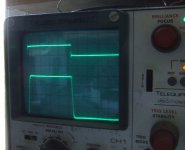
Below is the 10K square wave into 8ohm dummy load, input 1V P2P on the top, (yes I know my signal generator rings, I will get round to sorting it at some point! ) and output on the bottom.
edit, oh and R8=5.9 and R9=6.2
Below is the 10K square wave into 8ohm dummy load, input 1V P2P on the top, (yes I know my signal generator rings, I will get round to sorting it at some point!
) and output on the bottom.edit, oh and R8=5.9 and R9=6.2
Attachments
Good Morning Mike!
Okay, I've read this story a bit. The Symasym is now hooked up and making really nice music again. There is really no reason for it to sound this good jury rigged together.
Okay, let's allow it to warm up some...........
Right. R8 - 7.21/7.22 mV and R7 - 4.60/4.60 mV The slashes represent readings on R and L channels. No speaker loads. I would expect this since the driver beta's did vary by approximately that percentage. The output transistors were very close in beta. My bias current is approx 22 mA in keeping with my distortion measurements. Dropping the load resistance did not give me a different bias point. Higher bias currents only added more supply noise to the readings.
Now I'm going to hook up the speakers again and listen to it as I work.
-Chris

- Status
- This old topic is closed. If you want to reopen this topic, contact a moderator using the "Report Post" button.
- Home
- Amplifiers
- Solid State
- Troubleshooting your Symasym