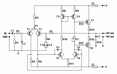
Please take a look at this schematic that i found at http://users.swing.be/edwinpaij/ampli_mosfet_simple.htm and tell me your opinion(or anyone in this forum),if it can be work well, at least it seems to be a decent circuit, with more controls to adjust it (I don´t want to explode mosfet´s because are more expensive that the BJT´s).
Even in this page there is an upgrade version of this amp with some components but that.
Also if somebody build it that write a comment
Thanks to all
Even in this page there is an upgrade version of this amp with some components but that.
Also if somebody build it that write a comment
Thanks to all
Attachments
marito,
you say mosfet is expensive, but according to ur schematic it is also a mosfet amp, I am familliar with that circuit, but I did not build that so far. it is uses a mosfet power of IRFP240 N TYPE, AND IRFP9240 P TYPE
u can visit aussieamplifiers it uses almost same topology.
rlg
you say mosfet is expensive, but according to ur schematic it is also a mosfet amp, I am familliar with that circuit, but I did not build that so far. it is uses a mosfet power of IRFP240 N TYPE, AND IRFP9240 P TYPE
u can visit aussieamplifiers it uses almost same topology.
rlg
Hi rlg_200,
Good points.
Caps and more punctuation would make your posts easier to read.
Hi Andrew,
-Chris
Edit: Marito, you have your own thread now!")
Good points.
Caps and more punctuation would make your posts easier to read.
Hi Andrew,
Agreed. This one is too long already.Hi Marito,
your in the wrong thread.
Try starting your own enquiry.
-Chris
Edit: Marito, you have your own thread now!
Originally posted by rlg_200 marito,
you say mosfet is expensive, but according to ur schematic it is also a mosfet amp, I am familliar with that circuit, but I did not build that so far. it is uses a mosfet power of IRFP240 N TYPE, AND IRFP9240 P TYPE
NO it certainly does not!!!
Anyone using IRFP parts in this configuration will get exactly what they deserve, and that is smoking IRF parts. This schematic is intended for lateral MOSFETs ONLY and is in fact an almost verbatim reproduction of an application note for Hitachi lateral MOSFETs. I am currently aware of only 3 manufacturers of lateral MOS, two being original (Hitachi and Magnetec) and the third, which name escapes me now, being a second source for obsolete Hitachi parts.
app note
Can you point us to this document?
Thanks,
Shawn.
ilimzn said:
...an almost verbatim reproduction of an application note for Hitachi lateral MOSFETs....
Can you point us to this document?
Thanks,
Shawn.
ilimzn said:I am currently aware of only 3 manufacturers of lateral MOS, two being original (Hitachi and Magnetec) and the third, which name escapes me now, being a second source for obsolete Hitachi parts.
Exicon?
AndrewT said:Renesas, Types include
2sj160/1/2 & 2sk1056/7/8
2sj81/2/3 & 2sk225/6/7
2sj48/9/50 & 2sk133/4/5
Thanks for info, Andrew! http://www.renesas.com/
Only Last week I had some idea for a Purist Lateral Power amplifier.
From some aspects, these great, but expensive! MOSFET
can make a good audio amp design a little bit more easy.
Good stuff at this page:
http://www.renesas.com/fmwk.jsp?cnt...ower_mosfets_for_amplifier/power_mos_gen_amp/
Code:
2SJ160	TO-3P	 	-7	PRSS0004ZE-A(TO-3P)
2SJ161	TO-3P	 	-7	PRSS0004ZE-A(TO-3P)
2SJ162	TO-3P	 	-7	PRSS0004ZE-A(TO-3P)
2SJ351	TO-3P	 	-8	PRSS0004ZE-A(TO-3P)
2SJ352	TO-3P	 	-8	PRSS0004ZE-A(TO-3P)
2SJ76	TO-220AB	 	-0.5	PRSS0004AC-A(TO-220AB)
2SJ77	TO-220AB	 	-0.5	PRSS0004AC-A(TO-220AB)
2SJ78	TO-220AB	 	-0.5	PRSS0004AC-A(TO-220AB)
2SJ79	TO-220AB	 	-0.5	PRSS0004AC-A(TO-220AB)
2SK1056	TO-3P	 	7	PRSS0004ZE-A(TO-3P)
2SK1057	TO-3P	 	7	PRSS0004ZE-A(TO-3P)
2SK1058	TO-3P	 	7	PRSS0004ZE-A(TO-3P)
2SK213	TO-220AB	 	0.5	PRSS0004AC-A(TO-220AB)
2SK214	TO-220AB	 	0.5	PRSS0004AC-A(TO-220AB)
2SK215	TO-220AB	 	0.5	PRSS0004AC-A(TO-220AB)
2SK216	TO-220AB	 	0.5	PRSS0004AC-A(TO-220AB)
2SK2220	TO-3P	 	8	PRSS0004ZE-A(TO-3P)
2SK2221	TO-3P	 	8	PRSS0004ZE-A(TO-3P)
lineup audio lab
>> lineup.awardspace.com <<
Hi,
The circuit is near identical to the original Hitachi aplication note.
And the 100W kit they used to sell in Maplins here in the UK.
I've had 3 in various bits of equipment, they all expired, presumably
due to unchecked parasitic output oscillations, its not a reliable circuit.
Also its very poor at utilising the full rail voltages driving low impedance
loads, the MOSFETs take up over 10V of swing each, not what you want.
All in all, avoid like the plague, and don't tell me it seems fine in a Simulator.
/sreten.
The circuit is near identical to the original Hitachi aplication note.
And the 100W kit they used to sell in Maplins here in the UK.
I've had 3 in various bits of equipment, they all expired, presumably
due to unchecked parasitic output oscillations, its not a reliable circuit.
Also its very poor at utilising the full rail voltages driving low impedance
loads, the MOSFETs take up over 10V of swing each, not what you want.
All in all, avoid like the plague, and don't tell me it seems fine in a Simulator.
/sreten.Hi everybody, very well discussions!!!
Anyway i want to know if somebody knows the way to replace P2 in the schematic http://users.swing.be/edwinpaij/ima...plisimpleV2.gif for a Vbe multiplier and his components,PLEASE!!!!
Cheers
Anyway i want to know if somebody knows the way to replace P2 in the schematic http://users.swing.be/edwinpaij/ima...plisimpleV2.gif for a Vbe multiplier and his components,PLEASE!!!!
Cheers
Hi,
leave P2 in place and add the Vbe multiplier around it.
Remember to also add the cap (100nF to 1uF) across the
multiplier.
Add zener (5v6 to 7v5) protection to the gate/source of the output FETs. Some say this and the existing rail fuses are all one needs to protect the output stage.
ps. what am I doing wrong? I still can't get it to link.
Marito said:Hi everybody, very well discussions!!!
Anyway i want to know if somebody knows the way to replace P2 in the schematic http://users.swing.be/edwinpaij/ampli_mosfet_simple.htm for a Vbe multiplier and his components,PLEASE!!!!
Cheers
AndrewT said:Hi,
leave P2 in place and add the Vbe multiplier around it.
Remember to also add the cap (100nF to 1uF) across the
multiplier.
Add zener (5v6 to 7v5) protection to the gate/source of the output FETs. Some say this and the existing rail fuses are all one needs to protect the output stage.
ps. what am I doing wrong? I still can't get it to link.
You are not doing anything wrong, AndrewT
not this time ...A little research and here is the full article of this project:
the images are in top class quality, like:
An externally hosted image should be here but it was not working when we last tested it.
You have it in French ( and in English ... if you like this any better )
Ampli MOSFET Simple
lineup
- Status
- This old topic is closed. If you want to reopen this topic, contact a moderator using the "Report Post" button.
- Home
- Amplifiers
- Solid State
- Please comment on this amplifier