Hi to you all
After searching a few times over the internet I finally came to the conclusion that there is no-one out there that has built Richard Burfoot's amp (as it appeared in Electronics & Wireless World, Nov. 1999) and posted some information about their experience with it.
Well, all this is about to change as I've decided to built it.
That was a year ago.
I have done nothing since then - many problems surfaced:
a) what inductor/transformer to use in the differential input stage
b) same for output stage
c) how to optimally mount the transistors on heatsinks
d) crossover/speaker interaction
etc.
Ok, now I will elaborate a bit on the above:
a) + b) :
Suffice it to say I want bass down to 8Hz.. not satisfied with the 40Hz the original offers. Ok, make that 20Hz and I'll be happy..
Well, as my electronics knowledge is only basic (I've never designed anything) I don't think I know how to choose and calc. the optimal inductance. Ie. I don't know how to choose the transformers/inductors.
I don't even know if pairs of inductors will do instead of transformer primaries (with the secondaries left disconnected).
I intend to use power supply toroids to keep the cost down but that shouldn't compromise the sound !
Could help me with choosing a toroid for the output stage ?
I'm even prepared to rewind one if that would lead to better results.
How about the input stage ? could I use a toroid there too ?
d) :
Another problem is that as this is a current amplifier, I have no idea how it will behave with my speakers as I don't know what the crossover their using is.
I would like some assurance it won't blow them up.
Well, seems like I've written enough already...
I'll post some more info depending on how much (if any!) response there is.
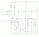
I should post a copy of the schematic for those people that have no access to it but it might take a little while as I can't just post a scan due to copyright reasons.
I hope it does generate some interest !
The features described above is what caught my attention but as I said, my electronics knowledge is basic so I don't know how this circuit will perform - I trust the author at that.
I've build an experimental circuit board and all I need to do is get the inductors and mount the power transistors (and then power it up :O )
Best regards
Stelios
After searching a few times over the internet I finally came to the conclusion that there is no-one out there that has built Richard Burfoot's amp (as it appeared in Electronics & Wireless World, Nov. 1999) and posted some information about their experience with it.
Well, all this is about to change
That was a year ago.
I have done nothing since then - many problems surfaced:
a) what inductor/transformer to use in the differential input stage
b) same for output stage
c) how to optimally mount the transistors on heatsinks
d) crossover/speaker interaction
etc.
Ok, now I will elaborate a bit on the above:
a) + b) :
Suffice it to say I want bass down to 8Hz.. not satisfied with the 40Hz the original offers. Ok, make that 20Hz and I'll be happy..
Well, as my electronics knowledge is only basic (I've never designed anything) I don't think I know how to choose and calc. the optimal inductance. Ie. I don't know how to choose the transformers/inductors.
I don't even know if pairs of inductors will do instead of transformer primaries (with the secondaries left disconnected).
I intend to use power supply toroids to keep the cost down but that shouldn't compromise the sound !
Could help me with choosing a toroid for the output stage ?
I'm even prepared to rewind one if that would lead to better results.
How about the input stage ? could I use a toroid there too ?
d) :
Another problem is that as this is a current amplifier, I have no idea how it will behave with my speakers as I don't know what the crossover their using is.
I would like some assurance it won't blow them up.
Well, seems like I've written enough already...
I'll post some more info depending on how much (if any!) response there is.
I should post a copy of the schematic for those people that have no access to it but it might take a little while as I can't just post a scan due to copyright reasons.
I hope it does generate some interest !
The features described above is what caught my attention but as I said, my electronics knowledge is basic so I don't know how this circuit will perform - I trust the author at that.
I've build an experimental circuit board and all I need to do is get the inductors and mount the power transistors (and then power it up :O )
Best regards
Stelios
rough schematic
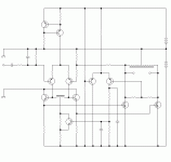
I've done a quick drawing of the schematic without any parts values yet.
The opamp is a discrete stage in the original but I didn't have the patience...
the transistors used are :
PNP's: ZTX214
NPN's: ZTX109
MOS : NDP6060
Apparently the idea from this came from a Mullard single ended amplifier that used germanium AD149's on the output (just in case you happen to have it ).
).
Quiescent current in the output is 3A per leg (total 6A through the battery). Lower battery is 12V and upper is 9V.
S
I've done a quick drawing of the schematic without any parts values yet.
The opamp is a discrete stage in the original but I didn't have the patience...
the transistors used are :
PNP's: ZTX214
NPN's: ZTX109
MOS : NDP6060
Apparently the idea from this came from a Mullard single ended amplifier that used germanium AD149's on the output (just in case you happen to have it
Quiescent current in the output is 3A per leg (total 6A through the battery). Lower battery is 12V and upper is 9V.
S
Attachments
There was an amp like that in Elektor about 20 years ago. It was intended to be used on 12 volts for mobile applications like busking (I actually know somebody from the Salvation Army who wanted to try it) etc.
They used the secondary of an ordinary center-tapped 12V/12V mains transformer. The performance figures (apart from power) were not very exciting but quite O.K. for the intended usage.
Regards
Charles
They used the secondary of an ordinary center-tapped 12V/12V mains transformer. The performance figures (apart from power) were not very exciting but quite O.K. for the intended usage.
Regards
Charles
Hi Charles
yes, the point of this amp is the efficiency. It claims 45% power efficiency and almost 377% voltage efficiency. This means it can run from a car battery and still present (I think) about 45V peak voltage on the output. Claimed power is about 32W for 72W consumption.
Stelios
yes, the point of this amp is the efficiency. It claims 45% power efficiency and almost 377% voltage efficiency. This means it can run from a car battery and still present (I think) about 45V peak voltage on the output. Claimed power is about 32W for 72W consumption.
Stelios
hmmm
overwhelming response so far ...
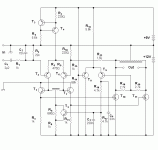
Well, nevetheless, here is a (final) corrected version with parts values this time. There was a small error in the feedback loop in the previously posted image.
The item I'm having most difficulty with is the first inductor/transformer. What I would like is some suggested inductance value for it (or how to calculate it) and possible parts that would fit the bill.
The second inductor I am pretty much certain it will be a mains toroid (say 230V primary - 40V sec. 225VA). Some companies make autotransformers with suitable values which would perhaps be preferable or indeed fabricate custom items. The questions I have on this item are:
- should it be rated for 3A (the quiescent current) or 6A (the peak) ?
- what VA rating should I aim for (the goal would be to keep leak inductance (& capacitance) low and hence not compromise the highs) ?
- do you have any suggestions for a company that will make custom items cheaply and will accept low orders (ie. only 2) ?
Finally, any other suggestions regarding parts substitutions, possible problem areas or general improvements, eg:
- would it be possible to remove the global feedback ? what other alterations should I make if I removed it ?
- should I replace the the current source or the dc servo with something better (and what) ?
Well, this is all I have to ask I guess.
In order to boost the interest a bit, I think I should add that the main other reason (apart from being an efficient class A amp) for building this is that it is a transconductance amp. or "current amplifier" if we want to abuse the terminology a bit. That "means" the input is a "voltage" and the output is "current". There have been one or two articles in E&WW singing the praises of such "current" audio amps but one should be carefull with large woofer excursions it might cause if uncontrolled.
One final reason is that it is quite easy to build although a little on the expensive side because of the large inductors and heatsinks and batteries required.
Best regards
Stelios
Attachments
Finally answers...
All my questions answered in this thread:
http://www.diyaudio.com/forums/soli...class-se-inductive-loading-3.html#post3346343
so I guess there's no point of this thread continuing...
Only took a decade but I guess it was worth it
All my questions answered in this thread:
http://www.diyaudio.com/forums/soli...class-se-inductive-loading-3.html#post3346343
so I guess there's no point of this thread continuing...
Only took a decade but I guess it was worth it
- Status
- This old topic is closed. If you want to reopen this topic, contact a moderator using the "Report Post" button.
- Home
- Amplifiers
- Solid State
- Inductance loaded current amplifier


