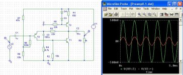
I have try to simulate ESP's P37.
http://sound.westhost.com/project37.htm
What I find out was: The preamp is inverted.
Should I do a inverted stage on the input or the output
so the preamp does not invert the signal?
Or it doesn't matterif if it's inverted?
(The main amp is not inverted)
http://sound.westhost.com/project37.htm
What I find out was: The preamp is inverted.
Should I do a inverted stage on the input or the output
so the preamp does not invert the signal?
Or it doesn't matterif if it's inverted?
(The main amp is not inverted)
roger-k said:I have try to simulate ESP's P37.
http://sound.westhost.com/project37.htm
What I find out was: The preamp is inverted.
Hi Roger
The project of preamp ESP P37 is no inverting ...
He's one hundred percent sure. Look at the orientation of Q3, it's common emitter, not emitter follower.
If your simulation actually shows it as inverting, you've made a mistake in drafting the schematic. Or it doesn't actually show that, and you're just looking at the wrong data.
If your simulation actually shows it as inverting, you've made a mistake in drafting the schematic. Or it doesn't actually show that, and you're just looking at the wrong data.
The software is Electronics Workbench
http://www.electronicsworkbench.com/
http://www.electronicsworkbench.com/
roger-k said:I have found an other pic of P37 on ESP.
I think this is very strange because I have beeb drawing the schematic, in the simulator, for many times now.
But is still inverted......
I think that our simulator is better in fiction , than in simulation...

Q1 and Q3 invert the signal. It should come out the same polarity as the input.
http://www.passdiy.com/pdf/mos.pdf
Repalce the Gate, Drain, Source with the Base, Emitter, Collecter for the bipolar.
http://www.passdiy.com/pdf/mos.pdf
Repalce the Gate, Drain, Source with the Base, Emitter, Collecter for the bipolar.
Would the phase shift if one of the transistors had a different Hfe as in more than the other one when it is supposed to have less? I don't think this happens in diffamp's though. You might want to check the Ic of each of the output transistors and see if one isn't functioning or something like that...
I am still a noober... Does Q2 act as a constant current source? Or does the ground connection act as input while the diodes produce a constant bias?
I am still a noober... Does Q2 act as a constant current source? Or does the ground connection act as input while the diodes produce a constant bias?
keantoken said:
I am still a noober... Does Q2 act as a constant current source?
Yes, Q2 is a CCS...
I think also that it is noninverted. The input transistor is working as common emitter feeding the lower transistor which is working as common emitter also (2 inversions making it in phase with input). The output taken from the collector of the lower trans with the upper trans working as the sink and not providing signal. There may be some inversion because of 90 deg. shift through input capacitor and another 90 deg from output cap. It may show up if taking input signal before the input cap and after the output cap.
Laugh at me if I'm wrong and I'll laugh with you
Laugh at me if I'm wrong and I'll laugh with you
doesn't matterif if it's inverted?
It seems to me that if the signal is inverted (regardless of why) when it reaches the speaker binding posts the simplest remedy is to reverse the connection..
this assumes you consixder there is anything that requires remedy.
- Status
- This old topic is closed. If you want to reopen this topic, contact a moderator using the "Report Post" button.
- Home
- Amplifiers
- Solid State
- Rod Elliot P37?