Hi guys
I build this classical MOSFET amp because I have some scrap:
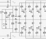
This is the PCB
Little photo :
:
Iknow is not the best design, is not the best sounding amp etc.. I build it for fun... so don't kick me
I have some trouble with it, the Vbe multiplier is oversensitive, if I set the bias (100mA per MOSFET) this slowly decrease as themperature increase and if I rebias at 100mA when the amp restart at cool the bias is over 100mA and I risk some thermal runaway....
Now I set the bias at 70mA ad is OK for the start, no runaway but after the heatsink is hot the bias get 50mA or less...
In your experience is happened thing like this?
Is there any solution?
Sorry for my bad english and thanx in advance...
bye
I build this classical MOSFET amp because I have some scrap:
An externally hosted image should be here but it was not working when we last tested it.
This is the PCB
An externally hosted image should be here but it was not working when we last tested it.
An externally hosted image should be here but it was not working when we last tested it.
Little photo
:An externally hosted image should be here but it was not working when we last tested it.
Iknow is not the best design, is not the best sounding amp etc.. I build it for fun... so don't kick me
I have some trouble with it, the Vbe multiplier is oversensitive, if I set the bias (100mA per MOSFET) this slowly decrease as themperature increase and if I rebias at 100mA when the amp restart at cool the bias is over 100mA and I risk some thermal runaway....
Now I set the bias at 70mA ad is OK for the start, no runaway but after the heatsink is hot the bias get 50mA or less...
In your experience is happened thing like this?
Is there any solution?
Sorry for my bad english and thanx in advance...
bye
you could try
to let the temp sensing transistor
have a bit less direct contact with heatsink
maybe put in some millimeter of some material
between this little transistor and the heatsink
this will make the temp adjustment a bit slower
and less sensitive to variations
from looking at your schematic
another way
exchange the MJE340 in your schematic
for a transistor
that better match the temp charateristics of those MOSFETs
http://img205.imageshack.us/img205/3648/200wmosfetvl4.gif
Often used is BD139
and there are a few other you can try to experiment with
also you might try putting those drivers
MJE15030 + MJE15031 onto a separate smaller heatsink
without temperature contact with main heatsink
luixssj3 said:Thanx for your reply, I'll try to put some space from Vbe mult and heatsink...
I'll let you know...
Yes, that is a good first try.
Sometimes it can be enough just loosen the screw a little bit.
I know old amplifiers, where the temp sensing resistor
was never in actually contact with heatsink, but very close to it.
Often used was NTC thermistor = Negative Temp Coefficient
is a resistor that gets lower resistance as temp get higher.
But also most transistors, like MJ340, BD139
has got a very linear negative coefficient.
Where Vbe ( volt from Base to Emitter pin ) sinks like 2 mV / per 1 degree C increase.
The hotter a transistor gets, the lower VBE gets.
In audio amplifiers
This gives a better control than using only resistors and/or thermistor for temp sensor circuit.
Still this is one detail that often require some trial and error.
To arrange this sensor in a way that gives perfect temp compensation,
is not that easy .. especially when you design an amplfier from scratch.
Now most experienced audio designers have this knowledge in their head
they know just about what will work.
This is why is no big problem if follow build instructions when you build
for example an audio amplifier by Professor Leach.
See reference link below!
Another good way, I did not mention:
Bigger Heatsink
When having these problems, it can often indicate,
you need a bigger HEATSINK for you appplication.
Big heatsink will not become as hot,
and so the overall effect will be just the same as
making Temp Sensor less senitive!
lineup
post became half an article, again ... why cant I keep it short?Appendix A.
Audio Related Things, by Professor Leach
http://users.ece.gatech.edu/~mleach/audiothings.html
Thanks for all the info!!!
I will trix with Vbe multiplier, I see some schematic have a diode on the emitter or a little resistance, I'll try it...
Distancing the Vbe transistor have some positive effect...
The heathsink is 20x10x5 centimeter, I think is OK, the themperature afther an hour is about 40°C you can still put your hand on it, maybe I'll try to put some fan...
Hi,
vertical FETs, is this what the amp was designed for?
Move the drivers off the main heatsink and keep them cool.
I prefer a small reduction in bias as the amp warms up and hopefully even less bias when it starts to overheat. A form of self protection.
The extra bias when cold is no problem and it helps get the devices up to temperature.
BTW. 200W into 4r from +-45Vrails is a bit optimistic. even 100W into 8r will be difficult (impossible?) to justify.
Nelson Pass said:I'm surprised that none of you have mentioned using a Mosfet
as the bias transistor in a Vgs multiplier - it's a lot less tweaky.
With bipolar drivers on heatsink?
Are you sure??
darkfenriz said:With bipolar drivers on heatsink?
You need more voltage to bias up a Mosfet output stage,
and a Vbe multiplier starts with .65V or so, but a Mosfet Vgs
starts with 3.5V or so, so there's less amplification required
of the Vgs.
I have used Vbe compared to Vgs in Mosfet follower amps with
and without bipolar drivers, and the Vgs are simply easier to
adjust. Thermal tracking is not problematic, and of course you
can tweak that more with positioning or with thermistors in the
network, although it's unusual to have to do so if you have
adequate sinking and/or Source resistance.
Nelson Pass said:I'm surprised that none of you have mentioned using a Mosfet
as the bias transistor in a Vgs multiplier - it's a lot less tweaky.
Can you show us some example???

@AndrewT: yes I "designed" (is a big word ) it reading document on the net and the presence of thermal compensation is for vertical devices as hexfet, if you know how to improve this amp I'm listen to you.
Yes 200W @4 and 100W @8 is an optimistic calculation
@jackinnj: yes I'm going to change to 5.6k or 6.8k because to have 100mA of idle current the trimmer is at 10 o'clock...
@Nelson Pass (the original GURU?) I never use a mosfet as Vgs multiplier, but I'll try it a day of this...
Many special thanx to all of you for your reply!!!
) it reading document on the net and the presence of thermal compensation is for vertical devices as hexfet, if you know how to improve this amp I'm listen to you.Yes 200W @4 and 100W @8 is an optimistic calculation
@jackinnj: yes I'm going to change to 5.6k or 6.8k because to have 100mA of idle current the trimmer is at 10 o'clock...
@Nelson Pass (the original GURU?) I never use a mosfet as Vgs multiplier, but I'll try it a day of this...
Many special thanx to all of you for your reply!!!
Hi,
6% imbalance between the LTP emitter currents seems a bit high.
The VAS is running at a high quiescent.
What about Zener protection for excessive Vgs?
Q. where to connect the Zeners?
direct across the gate to source?
or
from driver emitter to source?
or
from driver emitter to output track?
6% imbalance between the LTP emitter currents seems a bit high.
The VAS is running at a high quiescent.
What about Zener protection for excessive Vgs?
Q. where to connect the Zeners?
direct across the gate to source?
or
from driver emitter to source?
or
from driver emitter to output track?
Nelson Pass said:I'm surprised that none of you have mentioned using a Mosfet as the bias transistor in a Vgs multiplier - it's a lot less tweaky.
Used them in every class AB MOS amp I built! Also, used to mention them in these cases but since no-one seemed to pay attention...
Assuming a TO220 Vbe multiplier (unfortunately, not a common way to do this!), a simple replacement of BJT to MOS is needed, along with an adjustment of the resistor value between D and G, to set the proper multiplication factor (ideally the bias setting pot should be able to vary this from 2 to 3, depending on output MOS source resistors and chosen bias).
darkfenriz said:With bipolar drivers on heatsink?
Are you sure??
Yes, believe or not it does work properly in the majority of cases. The trick is that the Vbe change is just 'transmitted' to the MOSFET Vgs, which, due to lower gm is far less sensitive (thermal runaway is much slower in MOSFETs given the same idle dissipation and heatsink size), plus, due to high Vgs treshold, is even less sensitive since it's small in proportion to the Vgs. If there are source degeneration resistors, this is even more true - even a straight Vgs multiplier will overcompensate this.
In the rare cases where it might not be enough (single MOSFET pair with no source resistors driven by BJT drivers on the same heatisnk comes to mind), adding a thermally coupled diode in the MOSFET source does the trick.
Sorry I forget to draw zener protection on schematic, on the PCB is under the source resistor...
Is 9.1V 2W zener...
An externally hosted image should be here but it was not working when we last tested it.
Is 9.1V 2W zener...
luixssj3 said:I never use a mosfet as Vgs multiplier, but I'll try it a day of this...
If you want, you could take a look at the Vgs multiplier in passdiy: A75
Yes, I am really embaressed. Spending so much effort and text in this subject, trying to help a fellow member,Nelson Pass said:I'm surprised that none of you have mentioned using a Mosfet
as the bias transistor in a Vgs multiplier - it's a lot less tweaky.
and not really thinking of and mentioning MOSFET for Vbe thermal track

The closest I came was this where in my mind passed also use of MOSFET transistor:
lineup said:exchange the MJE340 in your schematic
for a transistor
that better match the temp charateristics of those MOSFETs
http://img205.imageshack.us/img205/3648/200wmosfetvl4.gif
Often used is BD139
and there are a few other you can try to experiment with
But this was a better information from me.
In this case it proved to be very true. Didn't it
lineup said:Now most experienced audio designers have this knowledge in their head
they know just about what will work.
This is why is no big problem if follow build instructions when you build
for example an audio amplifier by Nelson Pass.
Babowana said:
If you want, you could take a look at the Vgs multiplier in passdiy: A75
Thanks Babowana!
See my attached image from the old A75 paper by Norman Thagard and Nelson Pass.
IRF610 HEXFET ( TO220 ) is used as most basic setup Vbe multiplier
to thermally compensate for temp within an array of IRF230 / IRF9231 pairs.
This way to do it, would work as well, I imagine, if used for to thermally track
and compensate for popular IRF240 and/or IRF9240 pairs and all those similiar HEXFET.
Attachments
- Status
- This old topic is closed. If you want to reopen this topic, contact a moderator using the "Report Post" button.
- Home
- Amplifiers
- Solid State
- Simple MOSFET amp problem