Till,
I am not so sure you should expect to see the difference with
a scope. John Curl wrote about this on audioasylum once and
said that although they suspected a difference they couldn't
measure one, until somebody with access to RF spectrum
analyzers tried it. The oscillations you get can be of very high
frequency and are usually of very small amplitude compared
to the supply voltage, so it is very difficult to detect on a scope.
I have tried to simulate this in Spice some time ago and the
oscillation effect shows up, but that is only because one can
zoom into the signal in a way not possible with a scope.
Can you do FFT with your scope? Fundamental will be 120Hz, see how far down the harmonics and noise are.
If not, my scope can do FFT so I can post results from HEXFRED rectifiers. After the holidays, I suspect.
My spectrum analyzer only goes down to 9KHz which might not be low enough(?).
If not, my scope can do FFT so I can post results from HEXFRED rectifiers. After the holidays, I suspect.
My spectrum analyzer only goes down to 9KHz which might not be low enough(?).
christer, please say me the freyency resultution i need and the amplitude to expect. My fastest timebase i have here down to 10ns/cm without magnifier(manualsays good for 400MHz).
Amplitude may be the bigger problem because i have no better Y amp for less than 5mV /cm.
The scope can´t FFT, If anybody could say me the expected frequency, My PC does FFT but only up to 48kHz or so.
Amplitude may be the bigger problem because i have no better Y amp for less than 5mV /cm.
The scope can´t FFT, If anybody could say me the expected frequency, My PC does FFT but only up to 48kHz or so.
Till,
the problem is the realtive ratio of the oscillations and the
supply voltage. If you could apply a very sharp HP filter, then
maybe it would be possible, but that is just a guess. I can't
give you any good figures actually. It will depend on the diodes,
the inductance of the transformer, the resistance of windings
and leads to the bridge etc. The article on how to compute
optimal snubbers (can't find the link right now) gives you
formulas for this. For my Spice simulations I just choose a
value for the inductance, since my only purpose was to see
if I could get the effect to show up at all in simulations.
1st I would like to say thanks for this thread - been interesting so far - and worth my time.
I have found this additional info:
http://www.gensemi.com/appnotespdf/quik108.pdf
I have found this additional info:
http://www.gensemi.com/appnotespdf/quik108.pdf
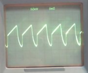
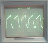
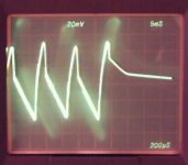
icceman said:The measurements were taken from the - & + of the bridge rectifier (without load) and the scope was set to AC coupled. I didn't record down the time base (I'm using the AUTO function of the scope) as I'm not really interested in measuring anything (just wanted to see the difference between standard and schottky rectifier).")
Load a rectifier bridge with only a probe has no meaning even if the curves are different. Of course you will get different curves. Think about the leakage of the diodes!
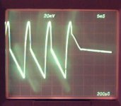
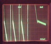
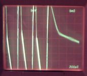
the first waves shown are with 5mS / cm. At the last its shown with 200uS / cm. You see at the beginning of this falling part of curve a little "undershoot" "antipeak", however it should be called in english.
With 50mV/cm its a little bit better to see, more isn´t possible because i have only a cheap X10 probe, and with a normal wire X1 i see nothing good anymore. (need better probes)
With 50mV/cm its a little bit better to see, more isn´t possible because i have only a cheap X10 probe, and with a normal wire X1 i see nothing good anymore. (need better probes)
Attachments
Lacking a spectrum analyzer, I've had trouble measuring
rectifier induced noise; it's low level compared to the
rectified waveform. A soft recovery rectifier should help minimize ringing in inductive circuits. Perhaps a cheap AM radio would
make a useable noise sniffer?
I found it helpful to put a snubber network across the transformer secondary to help control ringing. It's worse with
a small transformer, even with Schottky rectifiers. 100 ohms
in series with .47 uF seems to be a good starting point, there
is a definite null which can be 'tuned' with a resistor and a capacitor substitution boxes. Keep lead lengths as short as possible and use low-inductance stacked film caps.
I haven't found the nerve to try Schottky rectifiers on my Leach amplifier; I've only got 100 PIV units. I've tried HEXFREDs on
one channel which has been reliable and I just haven't gotten
around to building up a bridge for the other channel.
Seems like a shielded enclosure for the entire power supply would
be a good idea, though difficult to implement mechanically.
Has anyone done measurements in the current domain?
Sorry for bringing up a very old thread, but at least it proves I
searched the forum. Forunately my memory was right that it
was till who posted the scope pics, or I would probably never
have found the thread.
The reason I looked up this old thread is that I am currently
doing some experiments to see if I can measure any ringing,
which I seem not able too, but just as I remembered till
seems to have had success in capturing some ringing on
a plain scope image. Till, if you are reading this, do you remember
any data of the transformer you used, the caps size, the load etc.?
You give some such data earlier in the thread, but it is not clear
what the data are for the final measurements that show ringing.
I am using an 80VA toroid and a plain cheap standard bridge
rectifier. I've tried 470uF and 4700uF caps and various resistive
loads with load currents up to 0.5A and can see no hint of
ringing at all on my scope. Given what what has been said by
John Curl and others one probably shouldn't expect to see it
on the scope, but since till seems to have managed that, I
was curious to give it a try.
searched the forum.
Forunately my memory was right that itwas till who posted the scope pics, or I would probably never
have found the thread.
The reason I looked up this old thread is that I am currently
doing some experiments to see if I can measure any ringing,
which I seem not able too, but just as I remembered till
seems to have had success in capturing some ringing on
a plain scope image. Till, if you are reading this, do you remember
any data of the transformer you used, the caps size, the load etc.?
You give some such data earlier in the thread, but it is not clear
what the data are for the final measurements that show ringing.
I am using an 80VA toroid and a plain cheap standard bridge
rectifier. I've tried 470uF and 4700uF caps and various resistive
loads with load currents up to 0.5A and can see no hint of
ringing at all on my scope. Given what what has been said by
John Curl and others one probably shouldn't expect to see it
on the scope, but since till seems to have managed that, I
was curious to give it a try.
with 300VA + transformer, 12/16V, bridge, 10000yF and a real load (bulb)
The transformer is a very heavy EI, i estimate for more than 300VA, maybe 500VA with nominal 12V. The cap was an old 10000uF, Load a car lightbulb.
The scope is TEK7904 with 7A16A, 225Mhz bandwith amplifier, and 7B53A dual timebase.
It was best seen with using the dual mode of timebase and cheap diode bridge.
Thanks till,
that was a surprisingly quick response, especially considering that
the thread had been asleep for almost a year and a half.
You probably have a much higher load current then, so maybe
that has something to do with it? Do you know approximately
what the load current was?
that was a surprisingly quick response, especially considering that
the thread had been asleep for almost a year and a half.
You probably have a much higher load current then, so maybe
that has something to do with it? Do you know approximately
what the load current was?
Well, I don't have a very fancy scope, just a plain old 15MHz
dual trace from the late 70's.
Anyway, I tried with a passive HP filter with a pole around 16kHz
which rejects the ripple fundamental about 46dB (both calculated
and measured). Then I am at least able to detect a clear
undershoot on the load voltage (AC coupling the scope, of course).
There is also a slight trace of ringing on the order of a few 100uV,
but that seems to be some kind of background noise, not related
to the circuit. So, undershoot detected, but no ringing detected.
I also tried a two-pole filter, but still no ringing and it took away
a lot of the undershoot too.
The filter was only used for measuring the load voltage, the load
was still resistive.
I have done some systematic measurements now. The trafo
is as before and the bridge is a KBP204G rated for 2A, the cap
is 4700uF and the load is 60 Ohms, which gives a load current
of roughly 0.5A. Measurements were done using the one-pole
HP filter mentioned above and which cuts somewhere around
16kHz, rejecting the ripple fundamental approx. 46dB and with
the scope AC-coupled using a 1x probe. I should also mention
that I used a solderless breadboard for these experiments.
I varied two parameters: snubbers on the bridge and series
resistance between transformer and bridge. In no case could
I detect any ringing on the scope, but the voltage ripple over
the load measured through the HP filter showed an undershoot
spike.
I tried no snubbers, 1nF ceramics and 10nF polyester. I did not
try with resistors in series with the snubbers. None of these
three choices affected the undershoot.
I tried 0, 1 and 2 Ohms series resistance. This did affect the
undershoot, higher resistance giving less undershoot as
expected. The undershoot was as follows
R undershoot
----------------------------
0 Ohms 2.2 mV
1 Ohm 1.6 mV
2 Ohms 1.3 mV
So, there were no enormeous differences. Maybe a higher R
value also gave a slightly softer recovery, but I couldn't get
the precision to really measure it and it is just a, possibly
false, impression from what the curves looked like.
(Sorry, no photos. My digital camera can't capture scope
traces, and I don't think this is interesting enough to bring
out my SLR and waste ordinary film on.)
Edit: Are there some tags for formatting tables, or is it all
just plain HTML so I can use those tags?
- Status
- This old topic is closed. If you want to reopen this topic, contact a moderator using the "Report Post" button.
- Home
- Amplifiers
- Solid State
- Power Supply Freds, Hexfreds, Ultrasofts, Ultrafasts and Fast Recovery