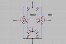
I have looked at the LTP topology and am wodering about it somewhat. I have some ideas that I am wondering about the ups and downs for. From what I know, here is a standard use of the LTP:
OUTPUTSTAGE is going to the output stage of the amp. OUT is the feedback output. Everythig else should be self-explanatory.
I have wondered about another idea I had and am showing in the next post.
OUTPUTSTAGE is going to the output stage of the amp. OUT is the feedback output. Everythig else should be self-explanatory.
I have wondered about another idea I had and am showing in the next post.
Attachments
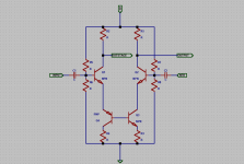
Here is my idea. The two bottommost transistors are complementary this time, making the bias flow through the emitters and collectors of the transisters. One downfall I can see to this is that the voltage on one side of the LTP is higher after this stage because the current flows one way. I also see that some complementary matching might be needed. Here it is:
Attachments
Hi, Keantoken,
You got many interesting ideas
I'm not familiar with your LTP in post#1. Usually a differential pair only consist of Q1-Q2 (without Q3-Q4) with both emitors tied together. This simple (but very powerfull) configuration of 2 transistors tied together in the emitors indeed does the main job of a power amplifier.
I'm interested in your idea, but could you explain it with LTP that only has Q1-Q2 without Q3-Q4, with Q1-Q2's emitors tied together?
By "You got many interesting ideas" I am supposing that is a good thing, thanks!
I am deriving this LTP variation from mikeB's symasym4 (in diagram).
I am not completely sure what you mean, as Q3-Q4 are the main points of my idea. Do you want me to explain how an LTP works so that you know I understand it?
I am simply wondering how this variation would work as supposed to the more used topology in my first post.
i am not really sure what Q3-Q4 are for (sorry... ), but I think that Q3 developes another comparing circuit with Q2 while using Q4 to amplify the input signal even more so that the output transistors can be biased at lower current therefore reducing noise generation (whew, long sentence!). Get what I mean? Am I right, mikeB? I think one of the ups of this idea is that instead of the bias current being split between the two bases, it runs through both bases at the same time, applying the full bias current to both transistors! (ohm's law might prove me wrong, though) Another intresting idea: I wonder what would happen if you fitted a resistor between the bases of Q3-Q4?
I severely dislike dissapointing people, so if I dissapointed you, tell me where I went wrong so that I can fix it next time!

I am deriving this LTP variation from mikeB's symasym4 (in diagram).
I am not completely sure what you mean, as Q3-Q4 are the main points of my idea. Do you want me to explain how an LTP works so that you know I understand it?
I am simply wondering how this variation would work as supposed to the more used topology in my first post.
i am not really sure what Q3-Q4 are for (sorry...
), but I think that Q3 developes another comparing circuit with Q2 while using Q4 to amplify the input signal even more so that the output transistors can be biased at lower current therefore reducing noise generation (whew, long sentence!). Get what I mean? Am I right, mikeB? I think one of the ups of this idea is that instead of the bias current being split between the two bases, it runs through both bases at the same time, applying the full bias current to both transistors! (ohm's law might prove me wrong, though) Another intresting idea: I wonder what would happen if you fitted a resistor between the bases of Q3-Q4? I severely dislike dissapointing people, so if I dissapointed you, tell me where I went wrong so that I can fix it next time!
Attachments
keantoken said:Here is my idea. The two bottommost transistors are complementary this time, making the bias flow through the emitters and collectors of the transisters. One downfall I can see to this is that the voltage on one side of the LTP is higher after this stage because the current flows one way. I also see that some complementary matching might be needed. Here it is:
OK, look at the voltage on the emitters of Q1 and Q2. Can you tell me what they are (approximately of course)? That will immediately show you whether this will work or not.
Hint: Assume that Vbe = 0.7V
Jan Didden
Hi, Keantoken,
If you know how a differential pair is working, you will understand other amp schematics (more complicated ones) more easily. Go to Nelson Pass' diy website, passdiy.com, read the article about Bride of Zen/BOZ, (or is it BOZOS?)
It is about 2 transistor of the same type, tied together in the emitors(sources for mosfets), and by making this 2 transistor differential pair with power devices, you already make an audio power amp that can move your speakers
Try to figure out how this 2 transistor tied together can make amplification of input in controlled way (certain dB constant gain factor with controlled DC offset, making linear amplification : out=K x input)
keantoken said:I am not completely sure what you mean, as Q3-Q4 are the main points of my idea. Do you want me to explain how an LTP works so that you know I understand it?
Yes, that would actually be a good idea since your first idea is not a LTP, i.e. does not function as such. The second would sort-of work like a LTP assuming resistor values are well chosen - except that it would add one more Vbe into one side of the LTP, and one pretty much wasted transistor in the 'tail' of the LTP, which in turn would prevent the LTP in doing what it does best - compensating the nonlinearities of one transistor in the LTP with tghe other (to put it simplistically).
Once again, I admire your enthusiasm, but you seem to be lacking some of the very basic knowledge you need to set up sensible electronic circuits - standard or unusual. For instance the difference between transistor emitter and collector, that the Vbe under normal active conditions equals 0.5-0.7V and if it is not, there is something very wrong, and, if the transistor was ideal, that you could NOT make it any bigger no matter what forward current you tried, etc.
Let me put this simply: you cannot use a hammer if you don't know which end to hold. Electronics is based on many 'tools' and many rules as to which end you hold them by to do work - but there are some basic ones, perhaps maybe a dozen or less. You need to lern them. Why? Well, because if this was, say, chemistry, you would be an interesting color, burned, or perhaps even dead - not all ideas are good.
Fortunately, this is electronics, and there is such a thing as a simulator - which has one serious failing: Unlike the real world, it does not explode, smoke or even tell you in any way that you had a bad idea - in fact, you have to look for it in the results it gives you to see it.
You have to learn to crawl before you walk before you run before you jump, there's no way around it - a simulator will just let you do it with less of the electronics equivalent of scraped knees, or, god forbid, broken bones, but, sadly, it will not tell you that you have scraped your knee or broken your bone, unless you alrady know HOW to interpret the result. And, to do that, you would need already what you are trying to get from the simulator. It's a chicken and egg situation, which means you must search for the basic knowledge somewhere else - books, courses, web pages (many!).
I am not really sure what Q3-Q4 are for (sorry...
...This is the first sign that you really should not be using it other than on it's own until you figure out what it does.
...amplify the input signal even more so that the output transistors can be biased at lower current therefore reducing noise generation (whew, long sentence!)
But one which could even be proved to be dead wrong! As I said - learn to walk first. Noise generation is the least of your concerns right now. And, FYI lower current does not necesairly mean lower noise.
(ohm's law might prove me wrong, though)
Ohm's lay is the one that you really need to take as an absolute in electronics. It works every time, and if you don't know where to use it, it will, as it were, bite you in the a$$ when you least suspect it.
[/b]
I severely dislike dissapointing people, so if I dissapointed you, tell me where I went wrong so that I can fix it next time!
Not knowing something is hardly a reason for dissapointing people - but asking questions in order to learn, and not listening to the answers you don't necesairly like, that is. Think about it.
Homework: function of current sources, and function of current mirrors. If nothing else so you can understand which part of MikeB's Symasym is actually the LTP
Base bias current willalways be half the tail current ina ny LTP - if it's not, it isn't a LTP - you might want to consider the answer to the question as to why this is so.
Oh yes - and if my answer anoys you - maybe it gives you incentive to figure out how to beat me over the head with my own words. If so, I will be happy, because then you will have figured out for yourself what you want to know - and once you do, that knowledge will always stay with you, unlike answers I could give you 'on a platter'.
Ah, yes... That last reply was kind of blunt, but I do think I might have just thrown the tightrope walker into the lion's den... I try not to be ignorant, but I try to learn the answers to all of my questions at first so that I don't have to run to a full-blown EE later just to figure something out. I think I'm just impatient. I don't just discard the answers that I don't like! That's not something a sensible person would do. I think it's lack of exposure/experience that gets me. I haven't really done anything with an LTP up till very recently, so I'm just trying to learn how it works. Sorry!


hi
here is an ordinary circuit using Long Tailed Pair input
it is a discrete op-amp
rather basic circuit
but nevertheless can produce HIFI
if put together and built in a good way:
more circuits from same DIY website
http://www.dibsplace.com/design/dcircats.html
lineup likes DIY Audio websites like this
here is an ordinary circuit using Long Tailed Pair input
it is a discrete op-amp
rather basic circuit
but nevertheless can produce HIFI
if put together and built in a good way:
more circuits from same DIY website
http://www.dibsplace.com/design/dcircats.html
lineup
likes DIY Audio websites like thiskeantoken said:Ah, yes... That last reply was kind of blunt, but I do think I might have just thrown the tightrope walker into the lion's den... I try not to be ignorant, but I try to learn the answers to all of my questions at first so that I don't have to run to a full-blown EE later just to figure something out. I think I'm just impatient. I don't just discard the answers that I don't like! That's not something a sensible person would do. I think it's lack of exposure/experience that gets me. I haven't really done anything with an LTP up till very recently, so I'm just trying to learn how it works. Sorry!
Well, I think one of the problems is to try to learn some basic stuff without asking the basic questions. You throw up circuits that give the impression you know all about them and want to discuss improvements. Naturally, you get info that is way above your head, like the previous post.
You could consider instead of asking: "this is a modified LTP, what do you think of the improvement" you could ask: "I think this is an LTP, can somebody explain how this works". If you do THAT, you make progress fast. If you do what you did before, progres is zero.
Sorry to be so blunt, but that's the score. I have 30+ years of analog design under my belt. There are MANY things I don't know. If I want to know them, I ask for explanation. I make progress fast. We were all born ignorant. The only thing you can be blamed for is refusal to learn.
Jan Didden
keantoken said:Ah, yes... That last reply was kind of blunt...{B]
Look, it is not my intention to chop your head off because you dared stick out a bit taller. Looak at what Janneman said - the point is, it is very difficult to understand something you don't, by trying to first modify it and observe what happens. At the very least you don't know where to look!
This sort of learning is only ever used as a last resort, and even then it is normally used only where you are trying to understand an observed phenomenon 'at gunpoint' (*).
LTP operation is ot an observed phenomenon - it was not 'found in nature' and it's workings deduced by observation and manipulation, it's function was not understood from it's form. It was invented, i.e. assembled with a particular purpose in mind, 'from scratch', knowing the intended function before the form took place.
This means that the idea of what you wanted it to do and to a large extent, how you make it do it, existed before the actual circuit. It follows that there is a wealth of knowledge about it - what exactly it does, how it does it, and why it does it. These are the basics you need to learn. THEN, you play with it - because the implementation of the idea is never erfect. But forst you need to understand the idea - or, if you want to be radical, trace the implementation backwards, to the idea. See if the idea is what you really need. Then try and figure out a different implementation - or start over with a different idea.
Your posts, to make an analogy, look like a mechanic trying to figure out how an engine works by randomly re-assembling parts of it in a different manner, to see what happens. Because the engine was made by people, you can actually ASK them what they were trying to accomplish - so why don't you? In the real world, these experiments would be costly and perhaps dangerous - you would likely give the whole thing up before you actually learned anything useful. In your case, it happens in a virtual world of the simulator, but the effect will eventually be the same, except less cost and no burned eyebrows. If you get pig-headed enough, the way you are going will eventually give you knowledge that some things dont work or blow up, but the question is, will you know WHY?
BTW you still owe us an explanation of how a LTP works, in your own words so we see you understand it
(*) What I described above is usually the last resort in medicine - because there is no-one to ask about the blueprints of the human body. But even then, no sane doctor would go this route without first extensively checking out on a vast library of knowledge previously gathered - by necessity, or because a 'modification' presented itself in a form of illness or defect and was then studied - point being, it wasn't introduced on purpose. As you can see, even in dire circumstances people first go to check on the existing lore. You are not in dire circumstances, so why not do this yourself?
Hi,
A Simulator is a great tool if you know what you are doing, if you don't ......
You need to read some good books. You need to understand circuit
design, the simulator only provides the details. You need to be able
to identify good and poor design, and why this is so. Common
topologies are exactly that because they work well, no-one is
interested in bizarre circuits that don't do anything useful.
http://en.wikipedia.org/wiki/Long-tailed_pair
Would help if you knew what a LTP is, the "long tail" is the high
impedance tail, shown above as a current source, you have a
pair with a current mirror load in your first circuit and no tail,
your second circuit simply does not do anything useful.
http://www.ecircuitcenter.com/Circuits.htm
Try the above for SPICE circuits.
/sreten.
A Simulator is a great tool if you know what you are doing, if you don't ......
You need to read some good books. You need to understand circuit
design, the simulator only provides the details. You need to be able
to identify good and poor design, and why this is so. Common
topologies are exactly that because they work well, no-one is
interested in bizarre circuits that don't do anything useful.
http://en.wikipedia.org/wiki/Long-tailed_pair
An externally hosted image should be here but it was not working when we last tested it.
Would help if you knew what a LTP is, the "long tail" is the high
impedance tail, shown above as a current source, you have a
pair with a current mirror load in your first circuit and no tail,
your second circuit simply does not do anything useful.
http://www.ecircuitcenter.com/Circuits.htm
Try the above for SPICE circuits.
/sreten.sreten said:
your second circuit simply does not do anything useful.
Actually, it could be used as an inverting level shifter of sorts
Sorry for the delayed response...
Okay, time to attempt to explain my idea of how an LTP works:
Input is injected at the base of Q1 and NFB is at the base of Q2. To get true comparison between currents/voltages, one of the transistors would have to be PNP, but as the feedback is already inverted, you can just use two NPN's. The simple idea is that when the current in one base rises, the current is the other should regress in the exact same manner and the amplified currents are mixed at the emitters. These currents should normally cancel each other out since as the current rises in one the current in the other decreases. The leftover current optimally would give an unvarying perfect current/voltage source. But if the output and the input of an amp are not exactly similar, then the unequal portions of the waves would not cancel completely and the leftover current would fluctuate according to the inaccuracy. This is the output of the LTP. This is sent to the input of the amp or another desired feedback point to correct the inacuracies of the output or input devices, therefore making the amp self-correcting.
How did I do? Probably not a college-level thesis, or anywhere near that, but tht is how I think an LTP feedback system works.
Sorry for wasting everybody's time...
Too long! You include a lot of other stuff like amplifiers that are not on the schematic.
KISS:
Assuming that the two transistors are reasonably matched, with NO input signal on either base, the tail current splits equally between the two tansistors.
If there is a difference in the two base signals, one transistor will increase its Vbe and the other will decrease its Vbe. Therefore, the two Ic's will also unbalance and one Ic will increase and the other decrease.
There, that's all there is. NOW you can use the LTP in ANY application where you need an output current difference from two voltage differences.
You also immediately see the basic limitation of the LTP: the relation between delta-Vbe and delta-Ic is NOT linear. Therefore, you need to take measures to increase the linearity (you have an example?) or to take care of that elsewhere in the circuit.
Jan Didden
PS Your explanation was pretty good, but you should start more basic.
keantoken said:Sorry for the delayed response...
Okay, time to attempt to explain my idea of how an LTP works:
... but that is how I think an LTP feedback system works.
Oh, stap bawling, you're not THAT bad and it won't help you
OK, what you explained is the latter, i.e. how a LTP is used in a feedback amp. Jan gave you the short version of how the LTP itself works. Here is another simple assignment: look above your post where Sreten posted a LTP (lower 2 BJTs) 'loaded' with a current mirror (upper two LTPs). Now, assume all transistors are equal, perfect, have infinite gain, and a fixed Vbe of 0.7V. Also assume the exact same input to both LTP transistors - i.e. they are tied together, and then to a voltage that ensures their Vbe is 0.7V. What would the output of this circuit be, as it is drawn now?
*Put's hand up*
Undefined.

Perhaps not the best conditions for analysis. It leaves you with a infinite impedance node with a consequently undefined voltage.
Better to analyze with perfect transistors and a small, but non-zero, input voltage, and then again with the opposite input.
Undefined.
Perhaps not the best conditions for analysis. It leaves you with a infinite impedance node with a consequently undefined voltage.
Better to analyze with perfect transistors and a small, but non-zero, input voltage, and then again with the opposite input.
Tim__x said:*Put's hand up*
Undefined.
Perhaps not the best conditions for analysis. It leaves you with a infinite impedance node with a consequently undefined voltage.
Better to analyze with perfect transistors and a small, but non-zero, input voltage, and then again with the opposite input.
Hi,
That not the point - the output when using a current mirror load
is a current - in the ideal world of a simulator the answer to the
question would be is zero current.

The above looks more like voltage output, again it is zero.
/sreten.Okay, another good training for keantoken given the above diffamp circuit from sreten.
Given values:
Only allowed tool is calculator, no sims.
Mike
Given values:
- -V = -6v
- +V = +6v
- all 3 resistors = 1k
- V+In and V-In set to -1v
Only allowed tool is calculator, no sims.
Mike
- Status
- This old topic is closed. If you want to reopen this topic, contact a moderator using the "Report Post" button.
- Home
- Amplifiers
- Solid State
- inquiries about LTP topology