In the past months open loop line stage designs have been discussed in general in the Blowtorch thread known to many frequent forum visitors and members.
Some topics have been explored to a certain extend and others just scratched on the surface.
My intention is to explore this kind of design with others in a constructive way which enables us to gain new insights on the design in general, as well as specific topics related to it. Apart from that I will try to post links with basic theoretical information so that the less academic schooled diy-ers, including myself, can have a better understanding of how the circuit works and what are key-issues. The Blowtorch thread already has a wealth of information thanks to John Curl, the designer of the well know Blowtorch pre-amp, so you might want to check that thread for additional information on the Blowtorch design itself. It may serve as a guide on our journey here.
Here we will deal with a similar design in general and explore its potential together. So your valuable input, experience and knowledge is welcomed.
We will start with the basic circuit which Justcallmedad a.k.a. JMCD has posted in the BT thread and which I use with his permission in this renewed thread (Thanks JMCD).
I cannot predict the course this thread will take, but would like to ask all participants to stay on topic as much as possible. Given the many areas this design encompasses, it may be mandatory to start a new thread for specific topics directly related to open loop line stage designs to keep the thread-flow as natural as possible and avoid information fragmentation. In this respect I welcome ideas from participating members.
Topics to explore or discuss are for instance:
- Determining gain
- Proper biasing
- Methods of achieving proper frequency response
- DC-Servo offset methods
- Noise-free power supplies, which are mandatory - for this design
- Improving the overall design
- Any other related topic which I may have forgotten
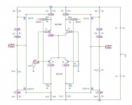
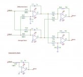
The following schematics serve as a basis: First the open loop cascade line stage.
Some topics have been explored to a certain extend and others just scratched on the surface.
My intention is to explore this kind of design with others in a constructive way which enables us to gain new insights on the design in general, as well as specific topics related to it. Apart from that I will try to post links with basic theoretical information so that the less academic schooled diy-ers, including myself, can have a better understanding of how the circuit works and what are key-issues. The Blowtorch thread already has a wealth of information thanks to John Curl, the designer of the well know Blowtorch pre-amp, so you might want to check that thread for additional information on the Blowtorch design itself. It may serve as a guide on our journey here.
Here we will deal with a similar design in general and explore its potential together. So your valuable input, experience and knowledge is welcomed.
We will start with the basic circuit which Justcallmedad a.k.a. JMCD has posted in the BT thread and which I use with his permission in this renewed thread (Thanks JMCD).
I cannot predict the course this thread will take, but would like to ask all participants to stay on topic as much as possible. Given the many areas this design encompasses, it may be mandatory to start a new thread for specific topics directly related to open loop line stage designs to keep the thread-flow as natural as possible and avoid information fragmentation. In this respect I welcome ideas from participating members.
Topics to explore or discuss are for instance:
- Determining gain
- Proper biasing
- Methods of achieving proper frequency response
- DC-Servo offset methods
- Noise-free power supplies, which are mandatory - for this design
- Improving the overall design
- Any other related topic which I may have forgotten
The following schematics serve as a basis: First the open loop cascade line stage.
Attachments
")
davidallancole said:Would a constant current source work in the differential amps to help the PSRR?
This jfet constellation already forms a ccs. But psrr is anyway degraded to ~-6db by the use of R6/4/20/16.
Mike
MikeB said:
This jfet constellation already forms a ccs. .
Mike
No. Should be instead of 203 ohm drain resistors.
You may be right.
Turning to shown circuits, what can be considered the best way to achieve an aimed frequency response for instance. In the second stage there is some local feedback applied which lowers the gain, but in the shown situation may not be sufficient or maybe not preferabel at all? What are your experiences or insights?
Turning to shown circuits, what can be considered the best way to achieve an aimed frequency response for instance. In the second stage there is some local feedback applied which lowers the gain, but in the shown situation may not be sufficient or maybe not preferabel at all? What are your experiences or insights?
My route is to fully understand and explore the possibilities such a circuit offers. As such it will be easier for me to build the configuration that suites my liking the most. Another reason is that currently I do not have the proper test equipment and the means to build several versions of this circuit.
PMA: The solid state devices used will affect the high frequency corner.
Can you elaborate on this. What exactly do you mean?
PMA said:No. Should be instead of 203 ohm drain resistors.
I thought he was talking about ccs feeding the diffamps. Yes, a ccs would help in place of the 203 ohms.
My main concern with this circuit is its psrr, my -6db were way to optimistic, i guess it's more like +20db. R5/6/16/17 really should be replaced by zeners. In this case a ccs intead of r2/3/19/21 would heavily help steady biasing, but also be overkill regarding complexity.
Anyway, the 4 ccs or the 4 zeners to keep the folded cascode steady !
I think no voltage regulator is quite enough to keep this circuit silent.
Mike
- Status
- This old topic is closed. If you want to reopen this topic, contact a moderator using the "Report Post" button.
- Home
- Amplifiers
- Solid State
- Open loop line stage pre-amp design revisited